Navigating THRUX
Workspace Toolbar
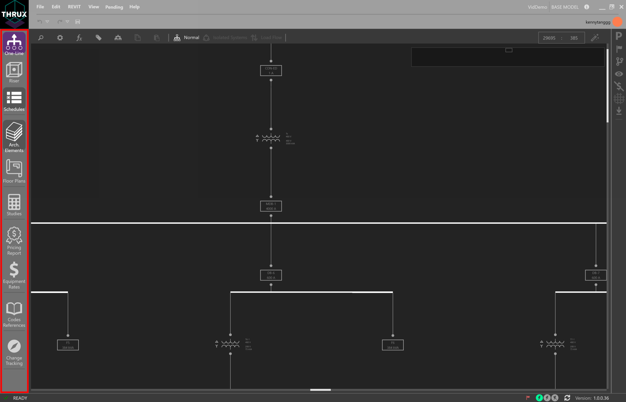
The left-side toobar is the Workspace Toolbar. The purple shading indicates an open and active Workspace, while grey shading only indicates an open Workspace.
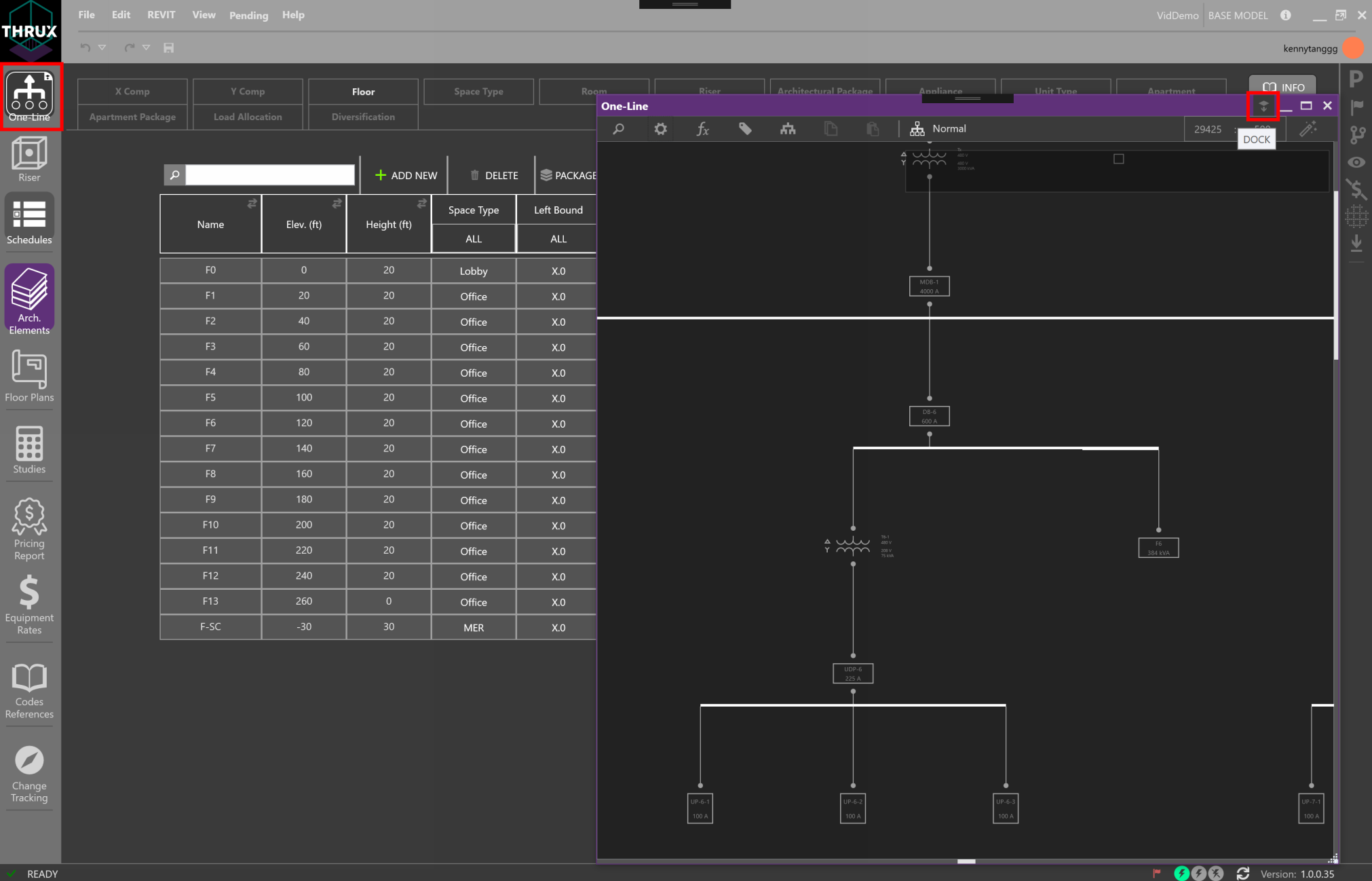
Workspaces can be hosted on different windows by dragging them outside of THRUX’s main window.
Bring these windows back into THRUX by clicking Dock in the top right.
Electrical Workspaces
The top three Workspaces, One-Line, Riser and Schedules, are the main electrical Workspaces to build the distribution system.
Architectural Workspaces
The next two Workspaces, Architectural Elements and Floor Plans, are mainly used to create the spatial elements that engulf or provide the structure to support the distribution system. These spatial elements will drive distances between Equipment that affect electrical calculations.
All of the Electrical Workspaces and the Floor Plans Workspace have the ability to zoom and pan. Press down or scroll using the mouse wheel to zoom and pan. The window shown below identifies where the current view is in respect to the entire canvas.

Pricing Workspaces
The Pricing Model mainly consists of the Pricing Report, Price Tracker, and the Equipment Rates Workspace.
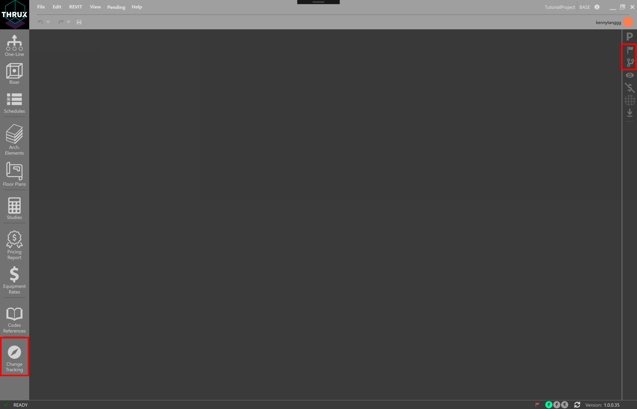
Project Management Workspaces
The Issuance Log allows for the creation of Branches. Branches can be used to study alternatives, and can also be compared to the base Branch by using the Change-Tracking Workspace.
Change Tracking allows designers to compare Branches of the Project. Results can be exported to an Excel document or by using Copy/Paste.
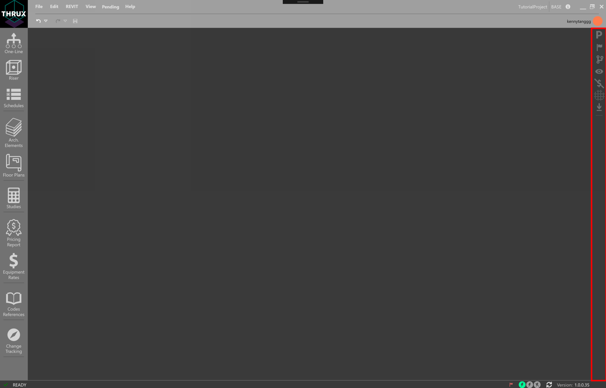
Explorer Toolbar
Explorers and other Utility tools can be found on the Explorer Toolbar on the right-side toolbar. These tools can be pinned to always be visible (pin icon).
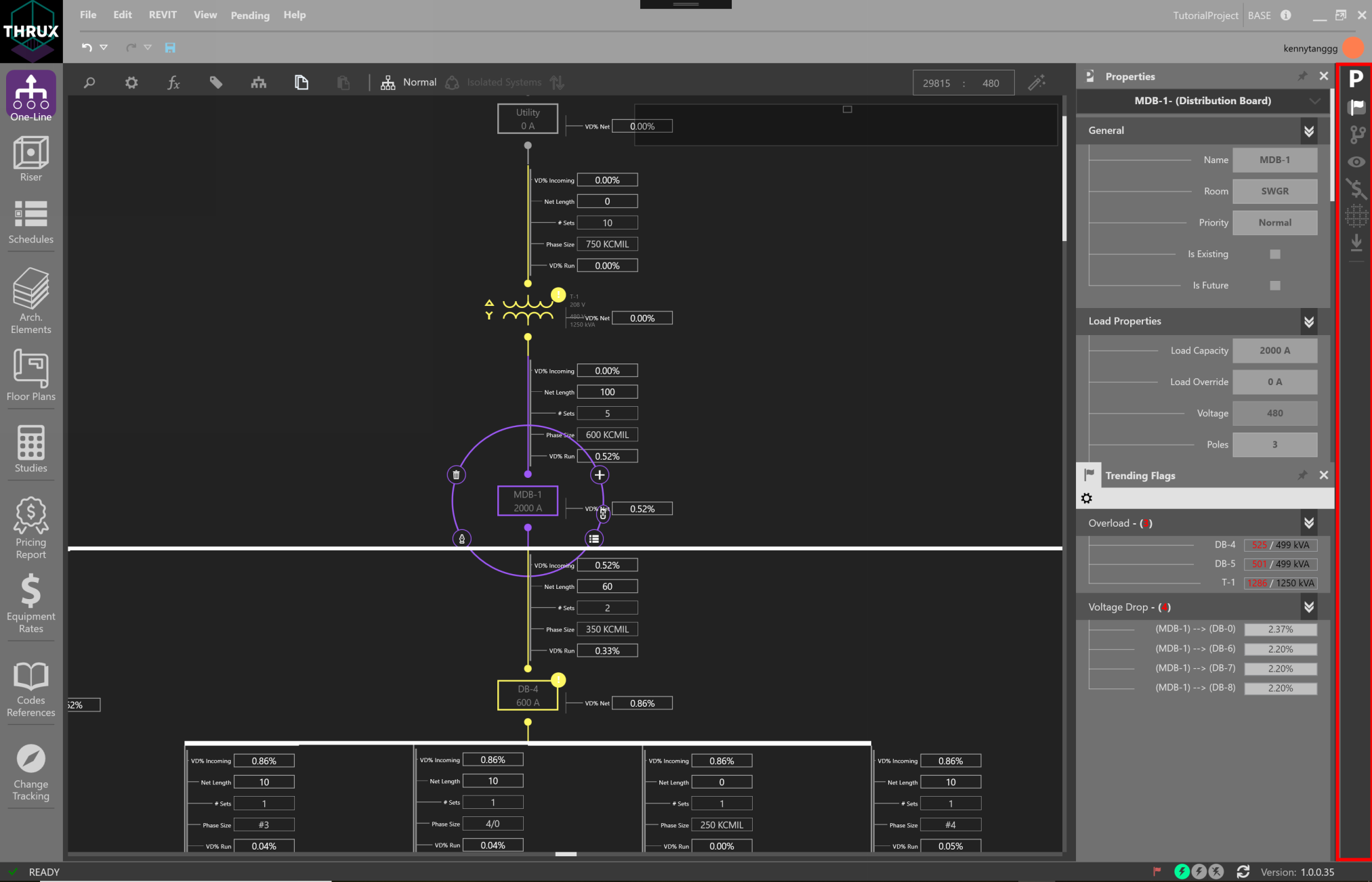
In the example above, the Properties Explorer and Flag Tracker are active, while working in the One-Line Workspace.
Properties Explorer
The Properties Explorer is used to display properties of the current selection.
Flag Tracker
The Flag Tracker live monitors Flags and errors in the model. Flags are violations of the Project’s applicable safety standards and codes.
Issuance Log
The Issuance Log gives the ability to create Branches, or Issuances.
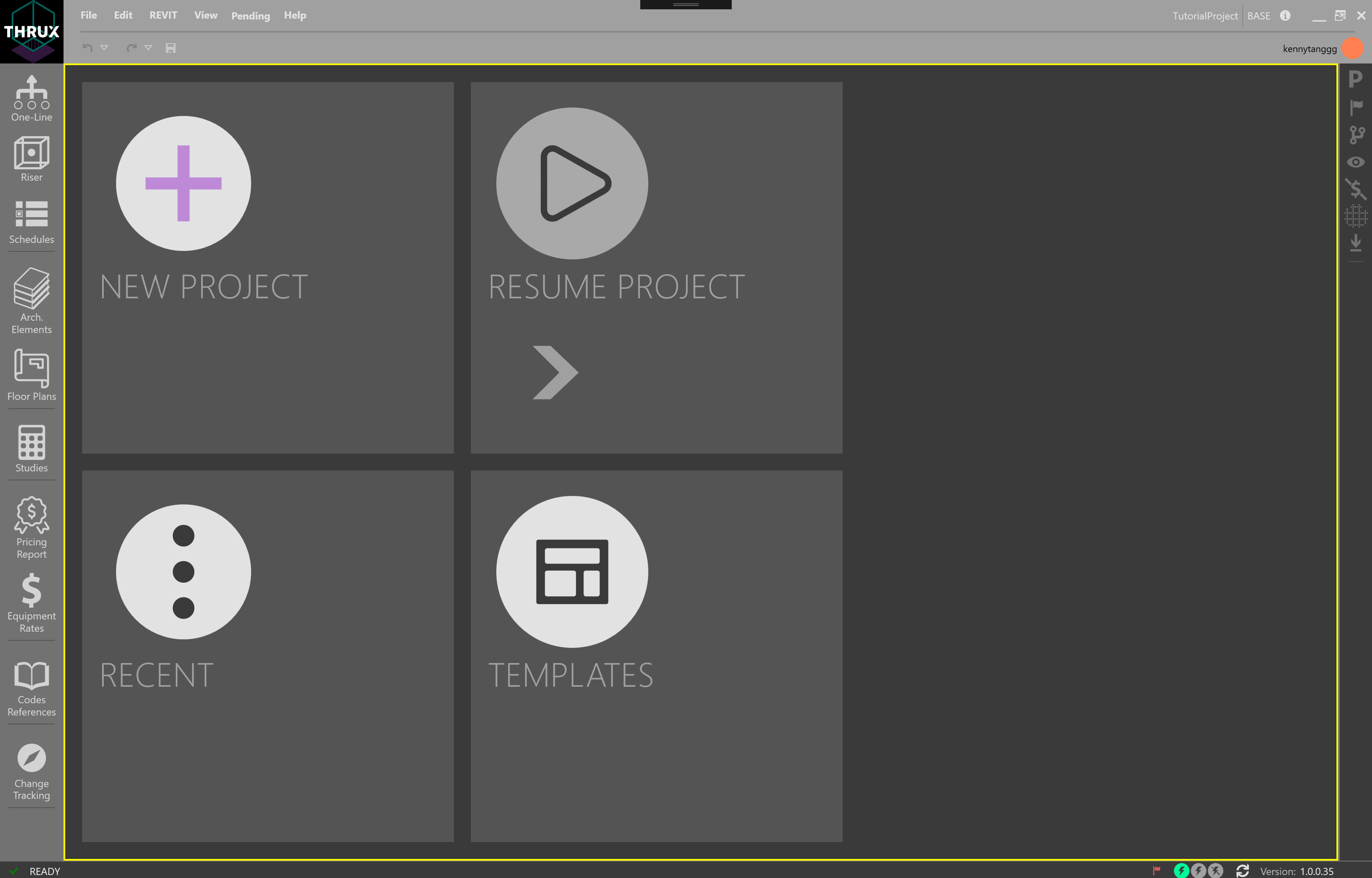
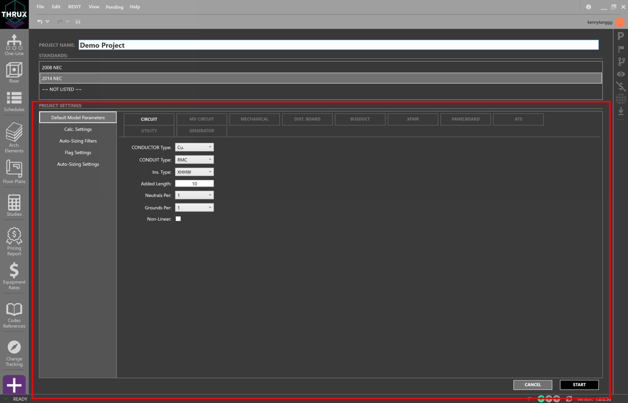
Creating a New Project
Click the Home button, and then the Add (+) button to create a new Project.
Project Settings
Project Settings are a set of customizable parameters on which to base the design.
Defining Architectural Elements
The goal of the Architectural Workspaces, Arch. Elements and Floor Plans, is to provide a way for designers to quickly mass the load of a building. These Workspaces create a skeletal structure of a building which can be used to house Equipment locations. These locations aid with point-to-point calculations such as voltage drop, which is a calculation based on the electrical load and the distance between the source and the load.
However, these Workspaces are completely optional. For a smaller project, you may not find it necessary to set up these Workspaces and instead, find it faster to manually input feeder lengths in the One-Line.
This information can be imported from an Architectural Revit model.
The Arch. Elements Workspace allows the designer to modify the architectural elements of the model. Here, it is possible to modify other characteristics of a Floor. For example, when massing the load of a building, a designer may want to assign a load requirement or load density to each Floor. This load is based off of the Floor’s Space Type.
These elements can be created in the Floor Plans Workspace, or the Architectural Elements Workspace.
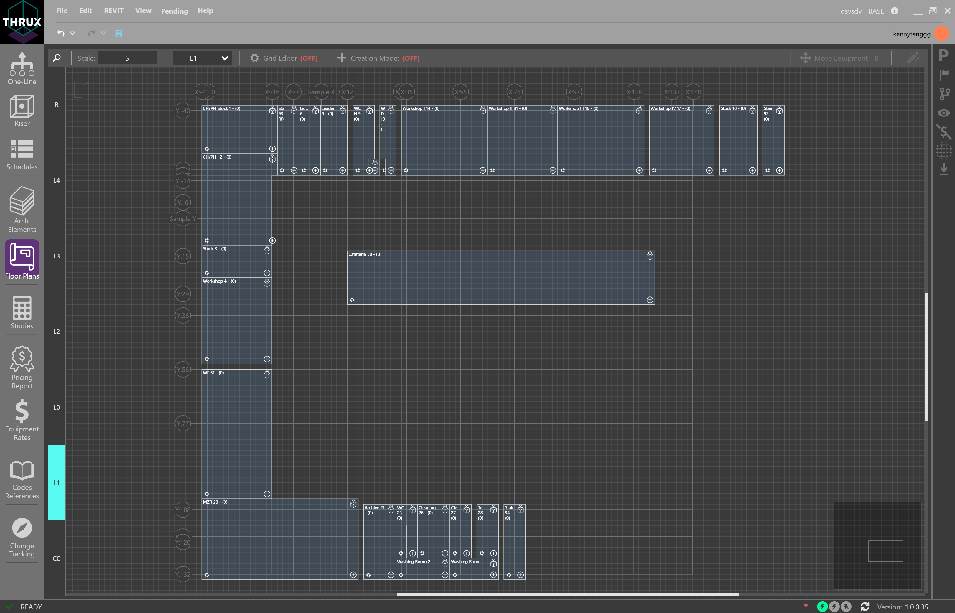
Floor Plans
Floor Plans are a 2-D representation of your project. Designers can create a combination of columns (XGrids and YGrids) and Floors to build a skeleton or framework. This skeleton can be used to model locations of equipment.
Revit Compatibility
The Architectural information which comprise the Architectural Workspaces, Arch. Elements and the Floor Plans, can be imported from a Revit model.
In addition, a THRUX model can be exported to Revit. Designers can then fine-tune Equipment locations using Revit, and verify the integrity of the design using THRUX.
Building the Electrical Model
There are three main Workspaces to build the electrical system are: One-Line, Riser, Schedules.
The goal of these Workspaces is to provide the best documentation for construction purposes, and it is important to note that information can be captured on multiple documents.
The locations of Equipment are determined by the Architectural Workspaces, Architectural Elements and Floor Plans, or can be determined manually.
At any time reports of a model can be generated using the Studies Workspace.
- One-Line
- Add a Source
- Add Equipment
- Copy/Paste Equipment
- Delete Equipment/Delete Network
- Dragging/Rehosting Equipment
- Navigate
- Expanding/Collapsing Equipment
- Changing Multiple Equipment Properties
- Reset to Code Minimum
- View Schedule
- Workspace Toolbox
- Creating a Transfer Switch
- Bus Duct
- Short Circuit Current
- Bus Node
- Schedules
- Riser
- Studies
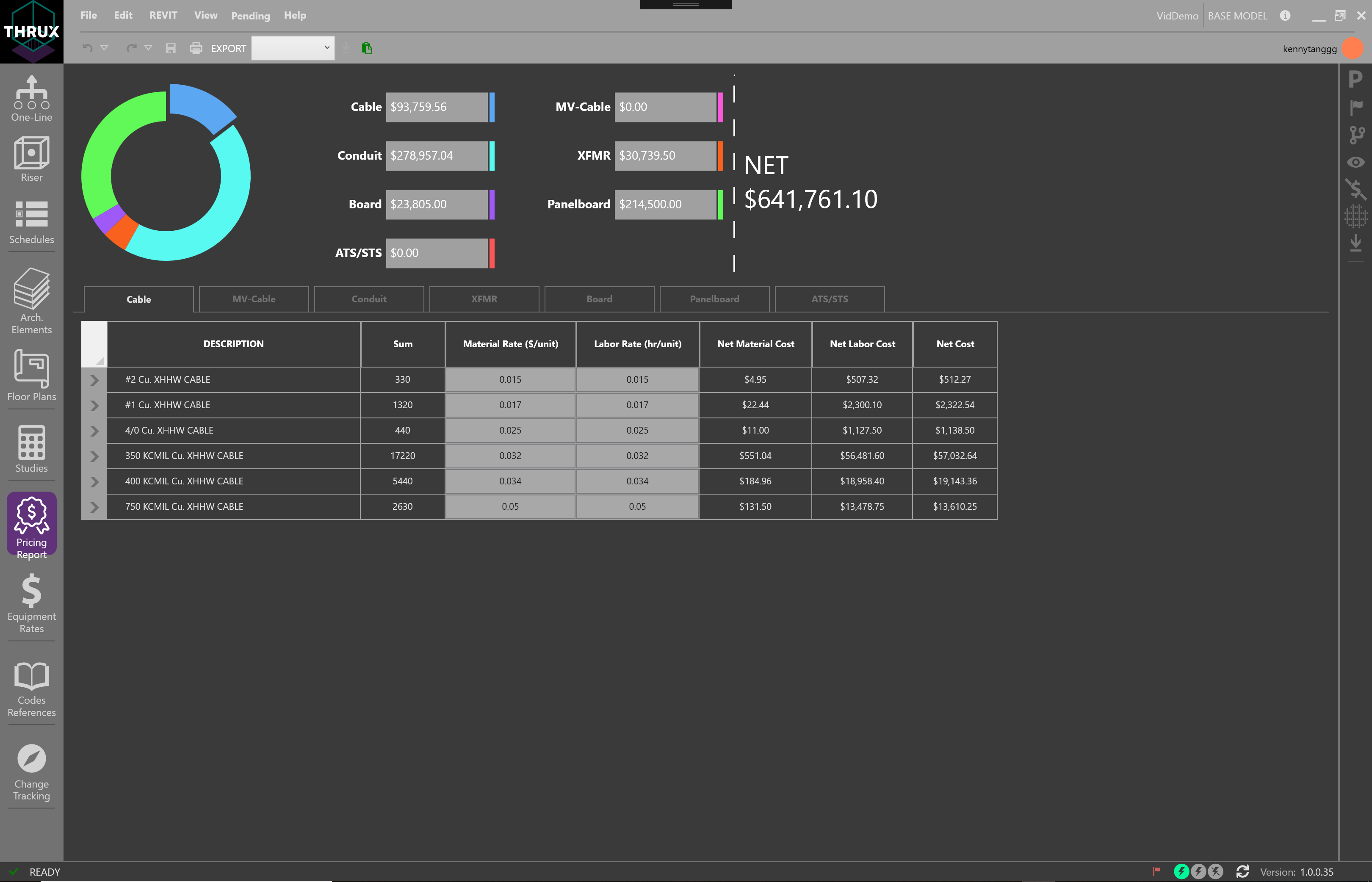
Pricing Model
The Pricing Model is built around the Electrical model and can be viewed in a few Workspaces. The Price Tracker is used to live monitor the price of the model. For example, as a designer changes the location of a major equipment room, the Price Tracker would display order of magnitude estimates for that change. For a more complete tabular report, use the Pricing Report Workspace.
Equipment Rates is a customizable catalog which composes the bid for materials.
Project Management
There are a variety of Project Management tools available to the designer.
Engineers are often tasked to study different alternatives or schemes and present them to the Owner. The Issuance Log allows the designer to create Branches.
The Change Tracking Workspace allows the designer to compare Branches against the base Branch.
The Flag Tracker displays a list of violations to a Project’s applicable safety codes and standards.
Explorers and other Utility Tools
The right-side toolbar of THRUX is generally where the explorers or utility tools are located. Explorers can be pinned to always be visible, while other explorers are being used.
- Properties Explorer
- The Properties Explorer presents properties of the current selection.

- Cascade Monitor
- The Cascade Monitor allows the designer to view the cascading effects of changes to the model in a line-item format.

- Scenario Manager
- The Scenario Manager allows the designer to create different Scenarios which toggle the state of specific protective devices.

- Data Exporter
- The Data Exporter allows the designer to export their data model in .csv, .xml, or .json.

- Codes Reference
- Codes Reference is a reference Workspace for safety codes and standards.
- Status Bar
- The Status Bar is located at the bottom of THRUX. It indicates different states of THRUX, and also provides access to other utility functions such as Design Assistance and Flag Toggling.

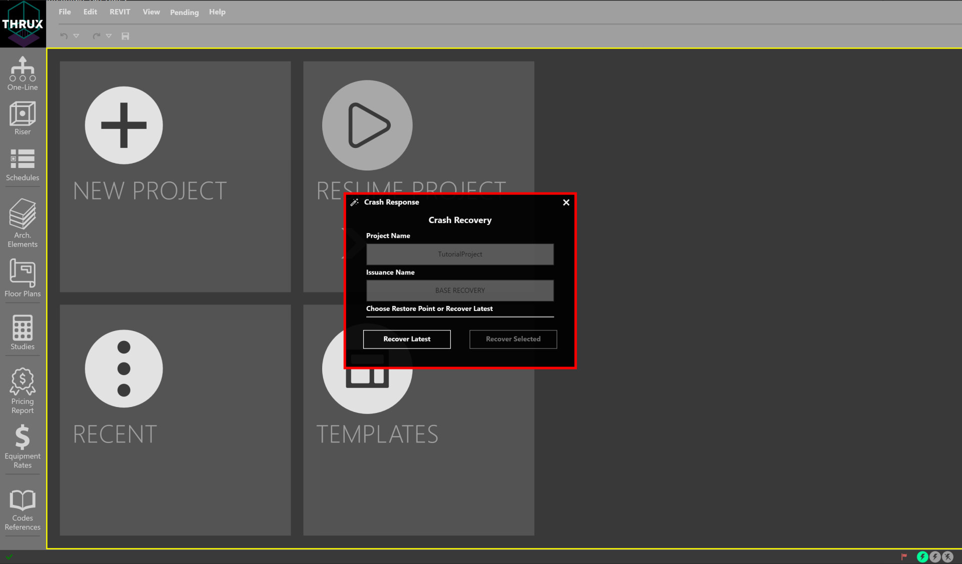
Recovery Options
THRUX models are stored in the cloud and are periodically backed up. If THRUX crashes, reopen THRUX. A recovery window will prompt to restore to the latest restore point, or an earlier restore point.
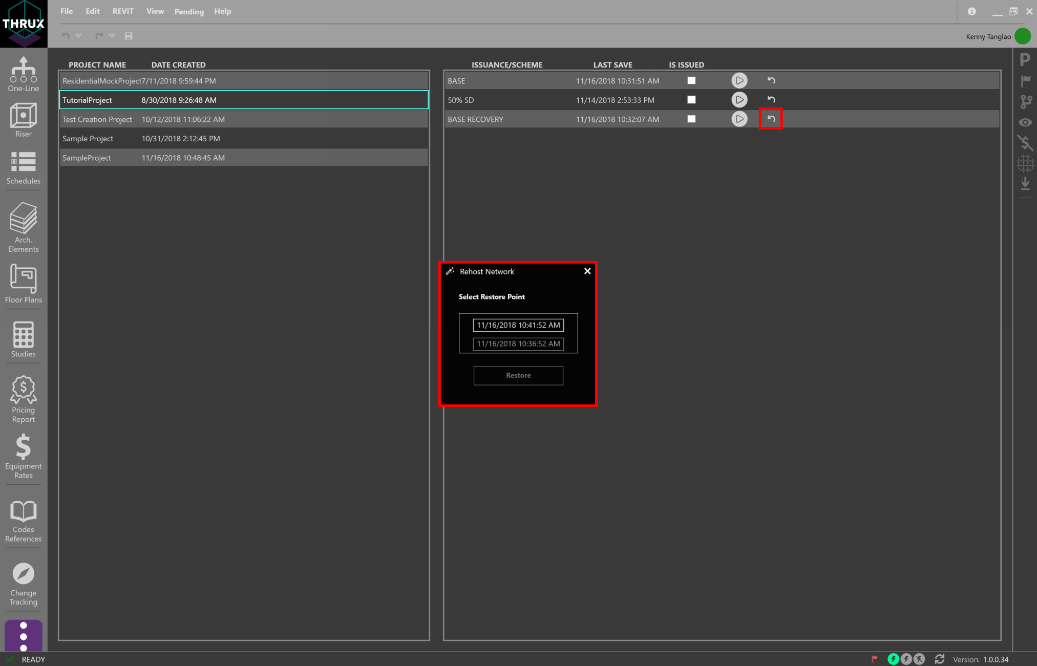
Another option is to restore a model to a restore point via the Open Project window. Use the Restore button (restore icon) and then choose a restore point.
Automatic Updates
Whenever THRUX is opened, it automatically searches for updates.
Refer to the Version Number in the bottom right of the Status Bar.

To see an outline of updates between each Version, click on the information icon located in the top-right of the top menu bar.
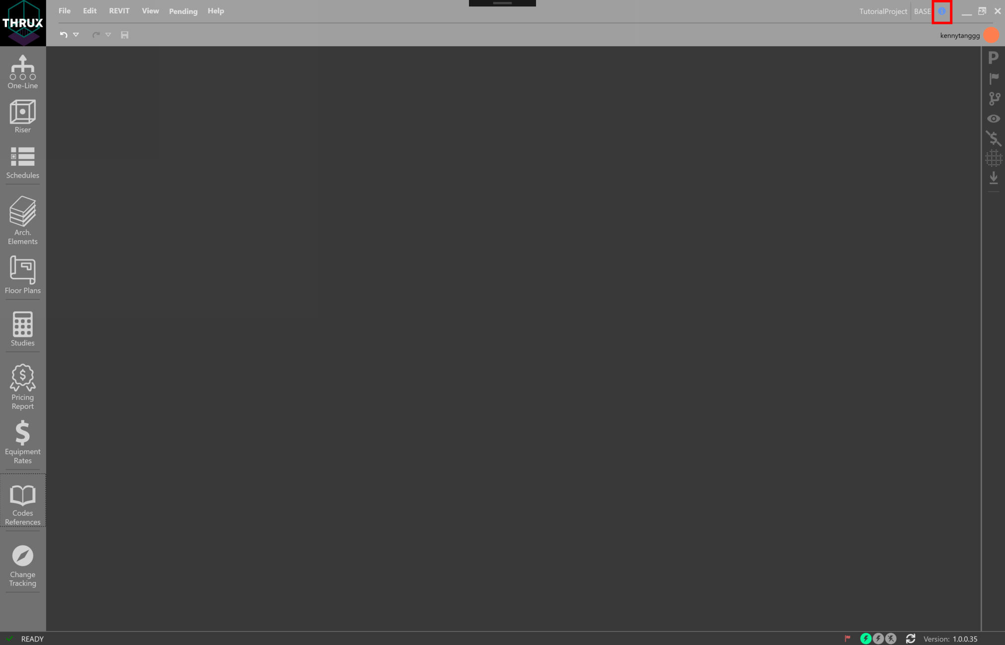
Use the arrows to navigate between each Version.
