One-Line
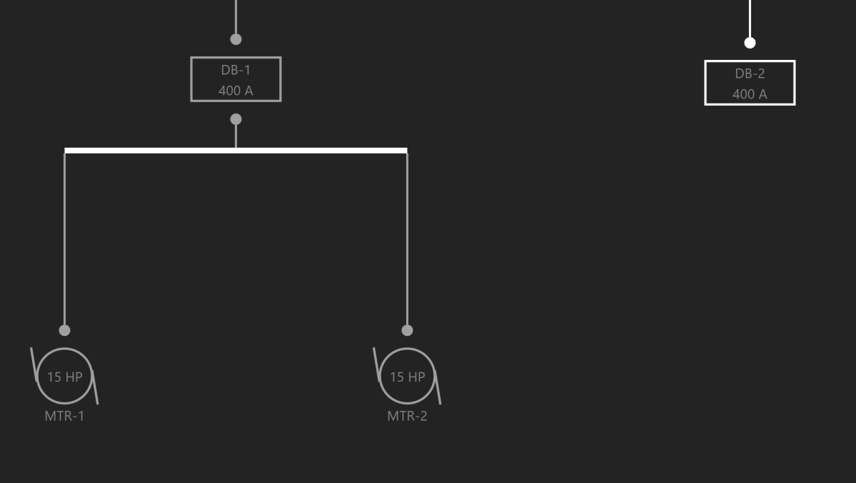
The One-Line represents power flow of the distribution system shown from top to bottom, and generally consists of Sources, Distribution Equipment, and Loads. All pieces of Equipment must be fed from a source. Types of sources include a Utility or a Generator. If a piece of Equipment is not fed from a source, then it is designated as Unhosted.
Using the Workspace Toolbar on the left, click the One-Line icon to open the Workspace.
Add a Source
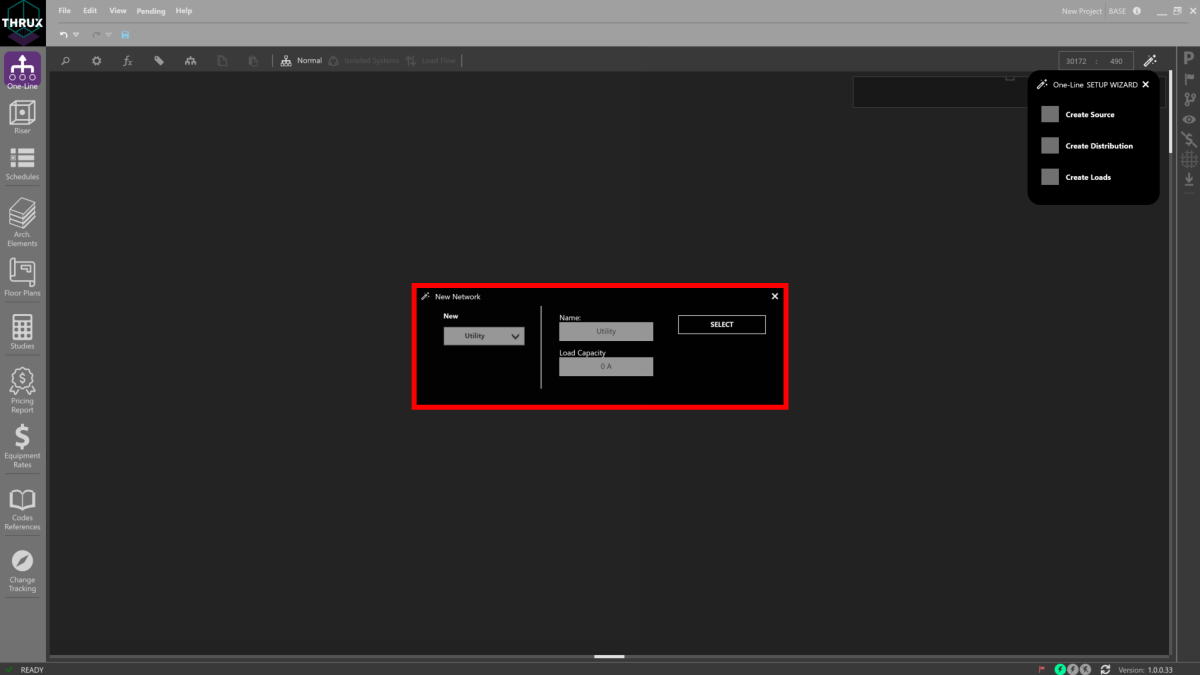
Use the Setup Wizard in the top right and select Create a Source.
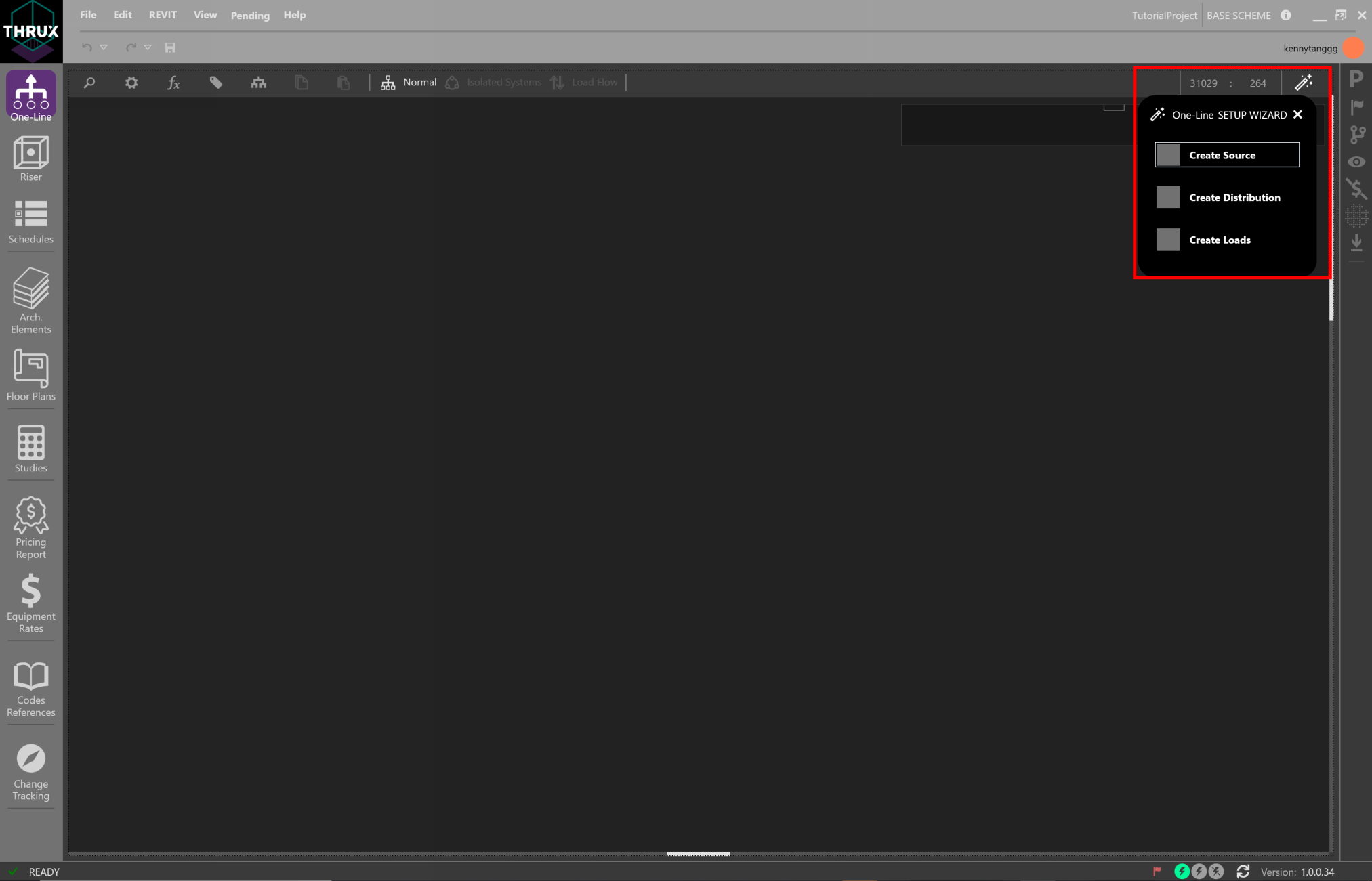
Using the New Network wizard, create a Utility Equipment.
Or right-click inside the Workspace, click Add Source, then click Utility Source.

Note that the ability to add Unhosted Equipment is available. Adding Unhosted Equipment can be used when the source of a network is unknown.

Add Equipment
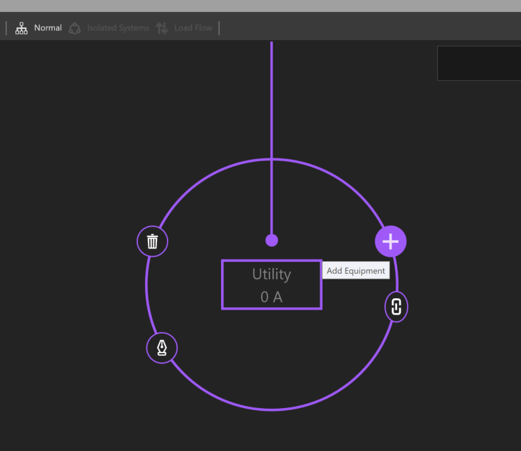
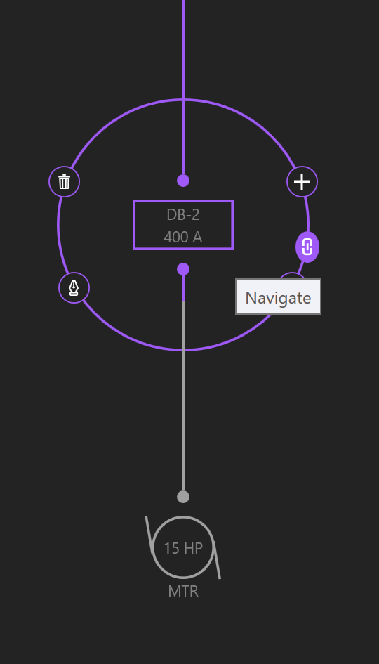
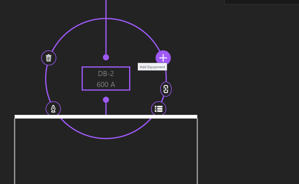
Click on the Utility and the Selection Dial will display a ring of options. Selected Equipment will be highlighted by a purple circle, with additional options to Add, Copy, Paste, Delete, and Navigate to other Workspaces. Click the + button to Add Equipment.
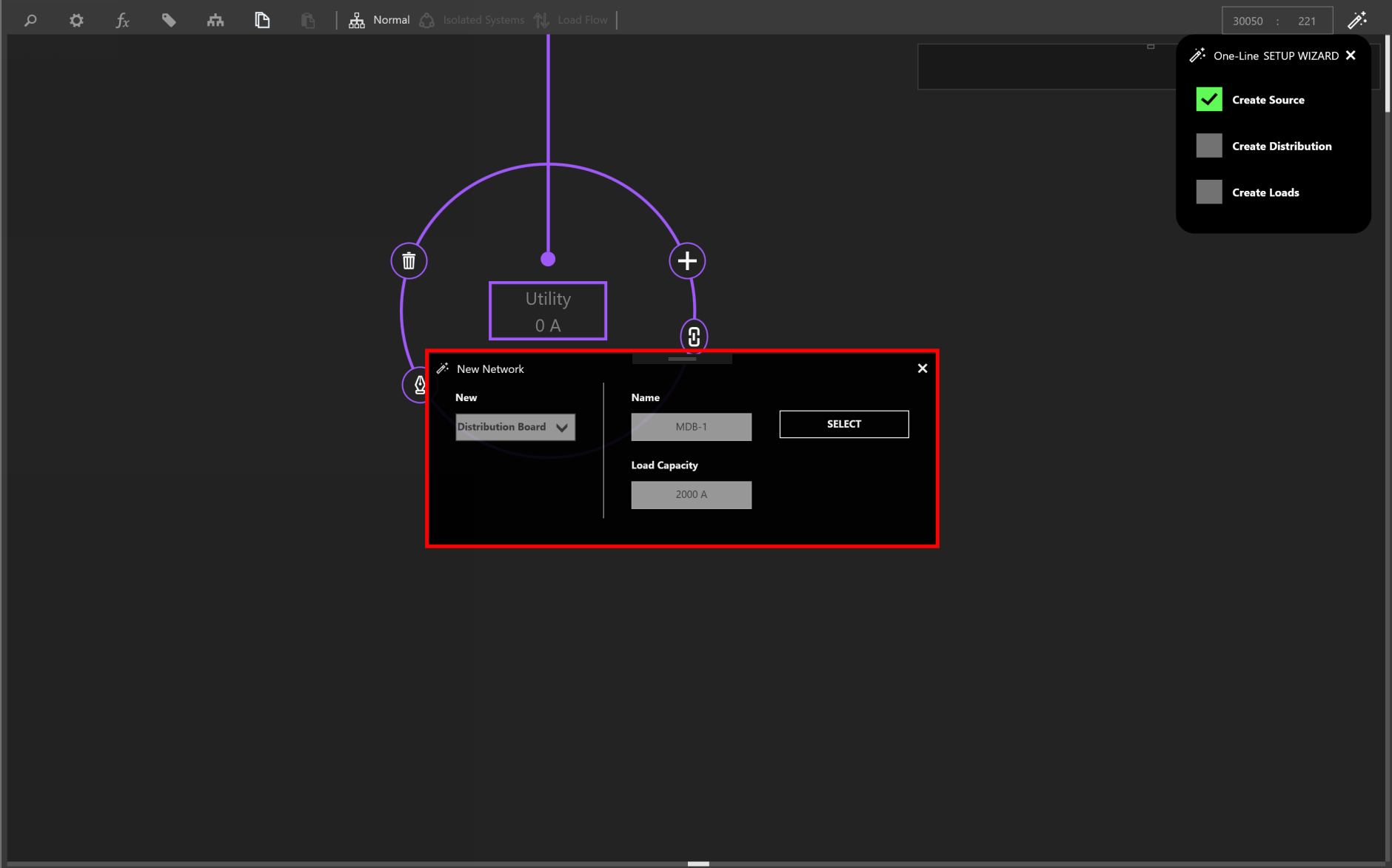
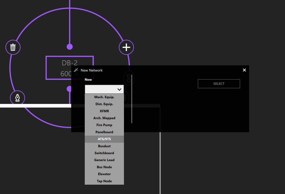
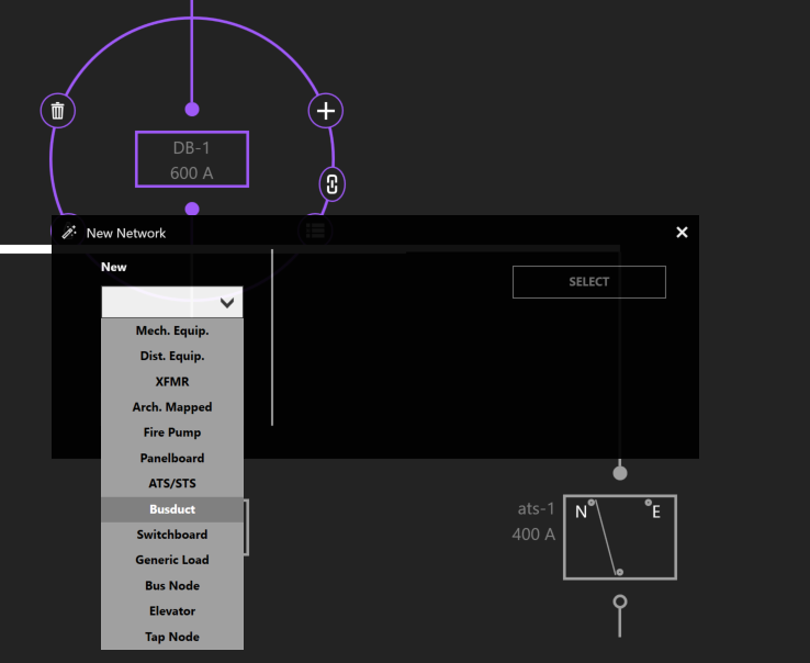
Select an Equipment type from the dropdown menu. Give the Equipment a name. In this case, specify a Load Capacity, and click Select.
Copy/Paste Equipment
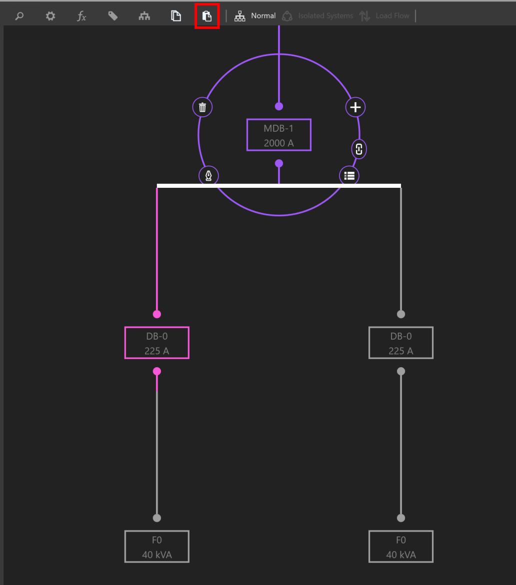
To copy Equipment, select the Equipment. Then, click Copy or use CTRL+C to copy. The selection will highlight pink and be added to the clipboard.
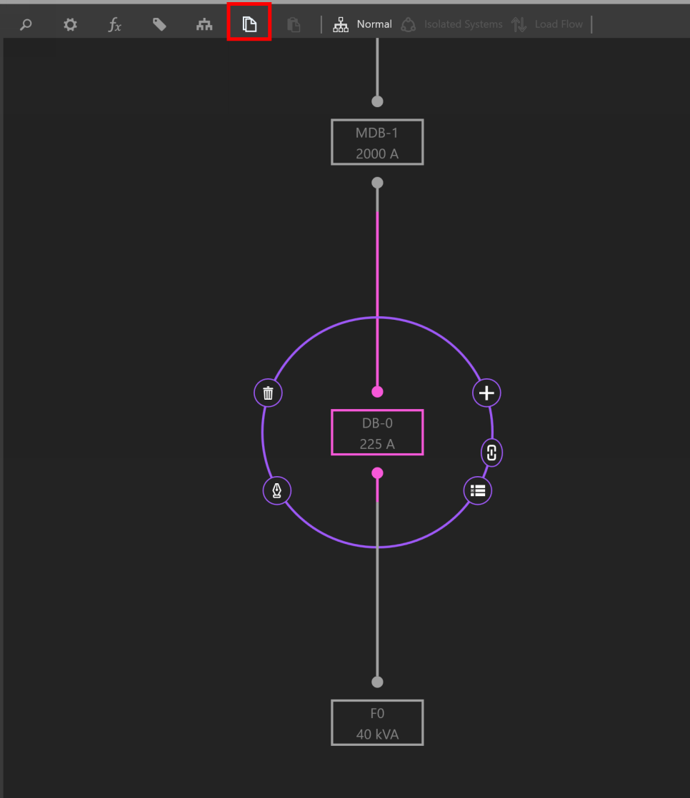
Then select the new source or Equipment to paste to, and click Paste or use CTRL+V.
Delete Equipment/Delete Network
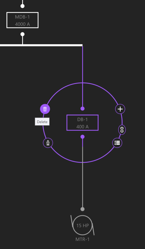
To delete Equipment, select the Equipment. Then Click Delete (trash symbol) or use DEL to delete.
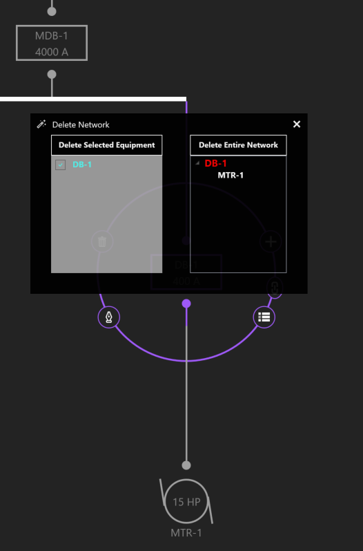
If the selected Equipment is feeding downstream Equipment, you can either delete the selected Equipment or the entire network.
Dragging/Rehosting Equipment
To redirect an Equipment’s source, click and drag the Equipment from its current source to a different source.
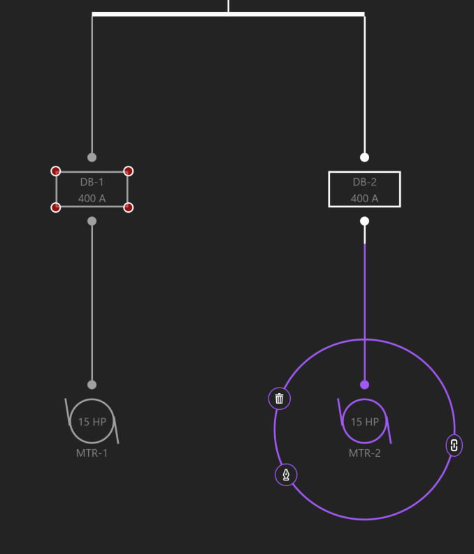
Drop or release the Equipment on its new source.
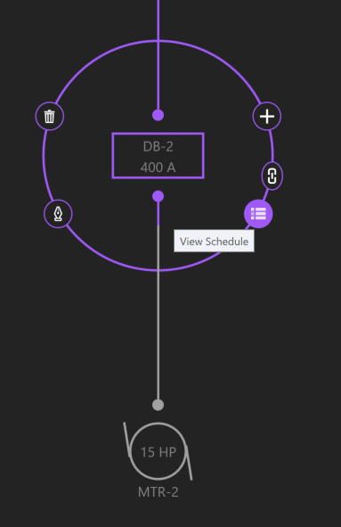
Navigate
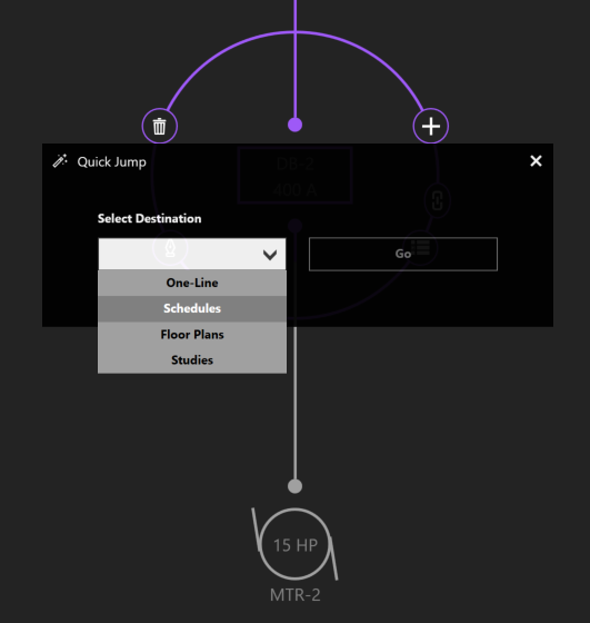
Navigate grants the ability to jump between Workspaces based on the current selection.
Other examples of navigation include viewing an Equipment’s Schedule, location on the Riser, location on the Floor Plans, or the Studies Workspace.
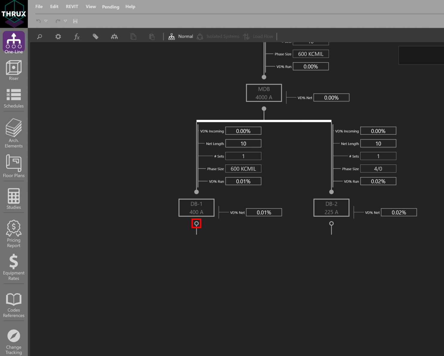
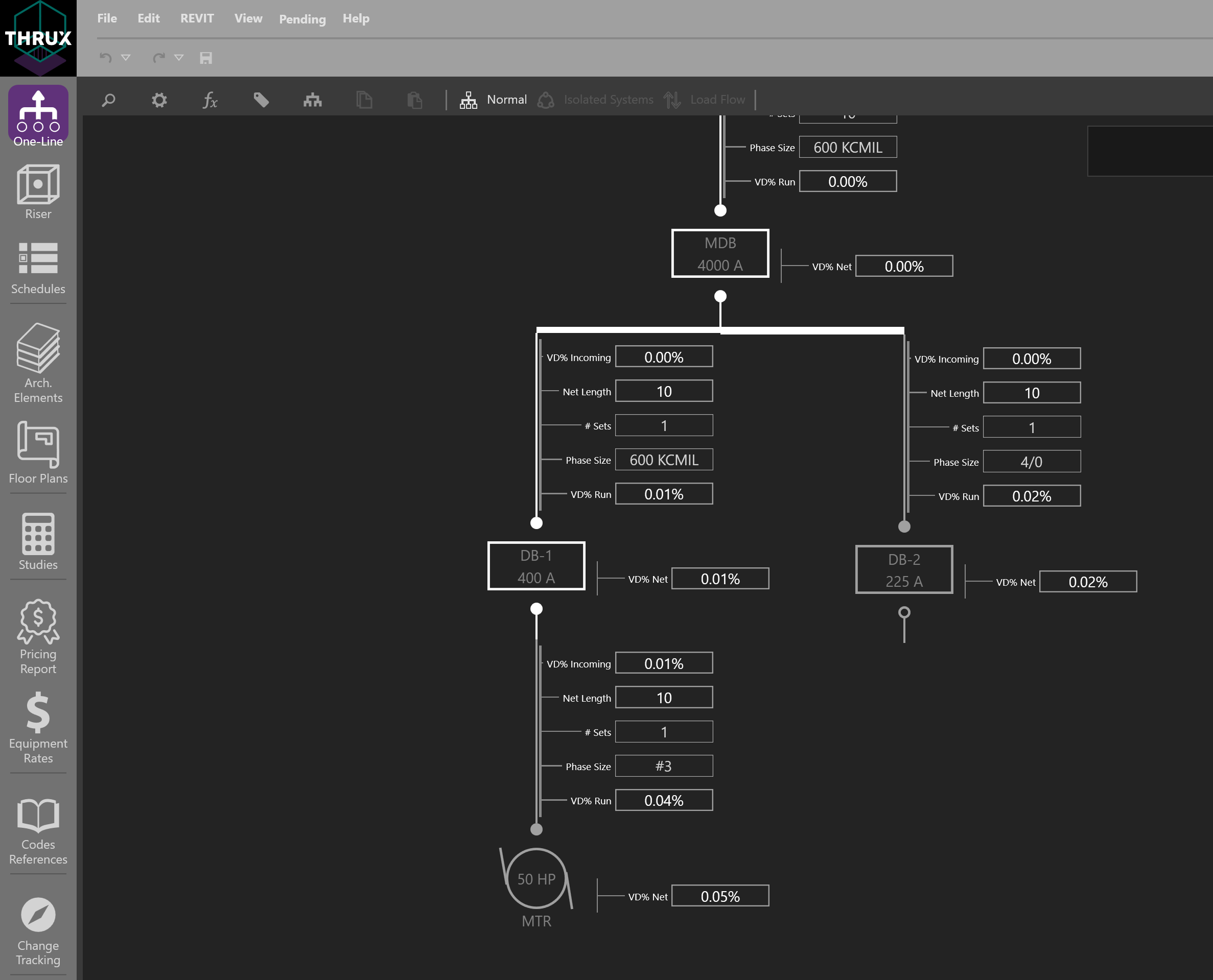
Expanding/Collapsing Equipment
Sections of the distribution network can be expanded or collapsed on a group basis by using Expand All/Collapse All.
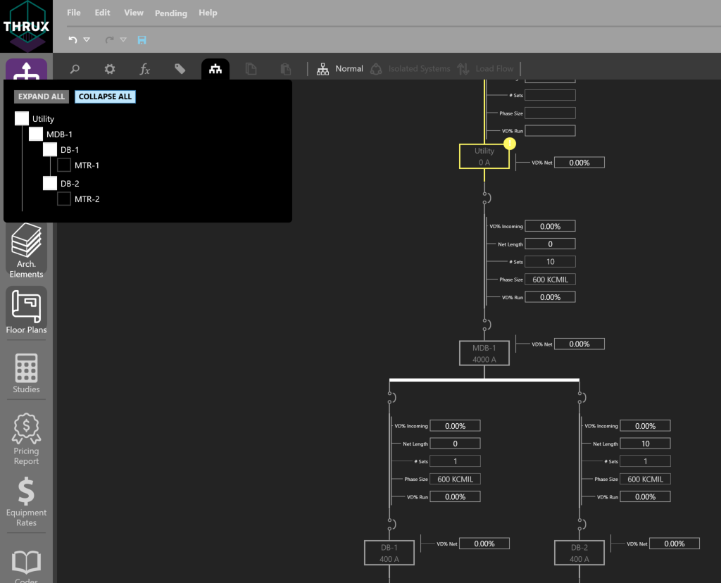
Another way is by double-clicking on a distribution node, or on the Equipment itself.
Changing Multiple Equipment Properties
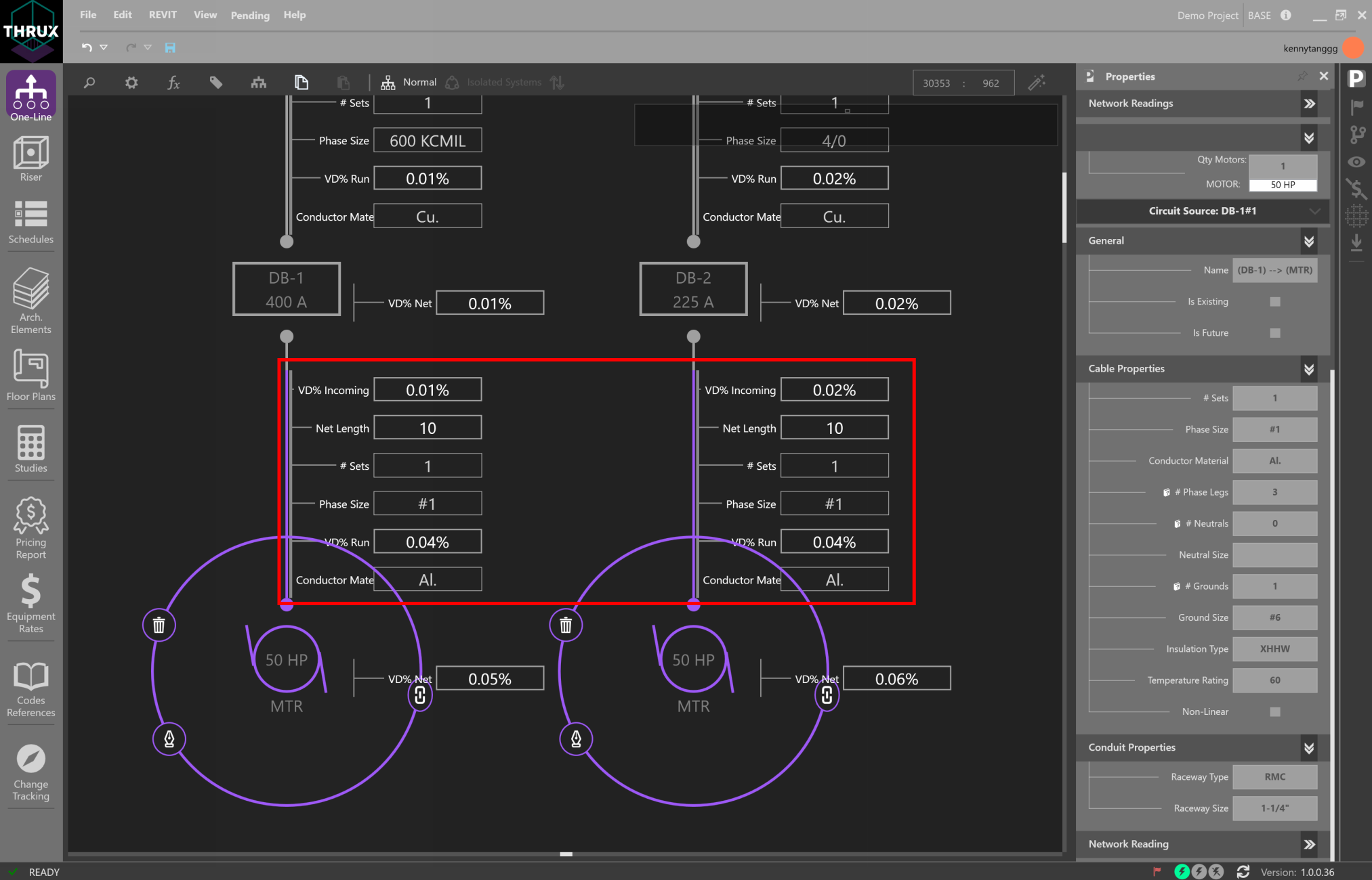
It is possible to change a property which is common across multiple elements. First, drag a box to select multiple elements, or use CTRL+Click to select each element.
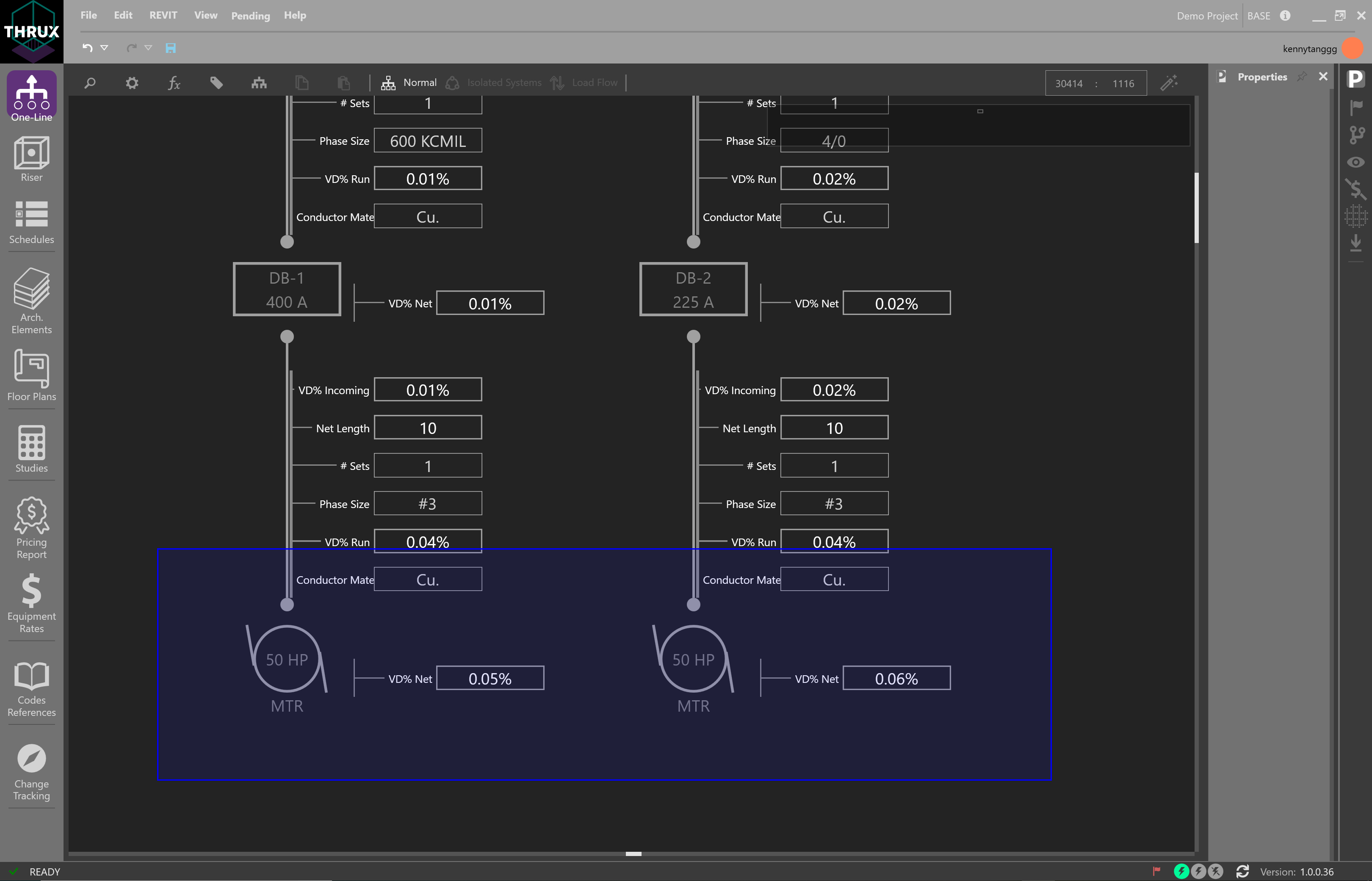
Then change a property such as Conductor Material from copper to aluminum.
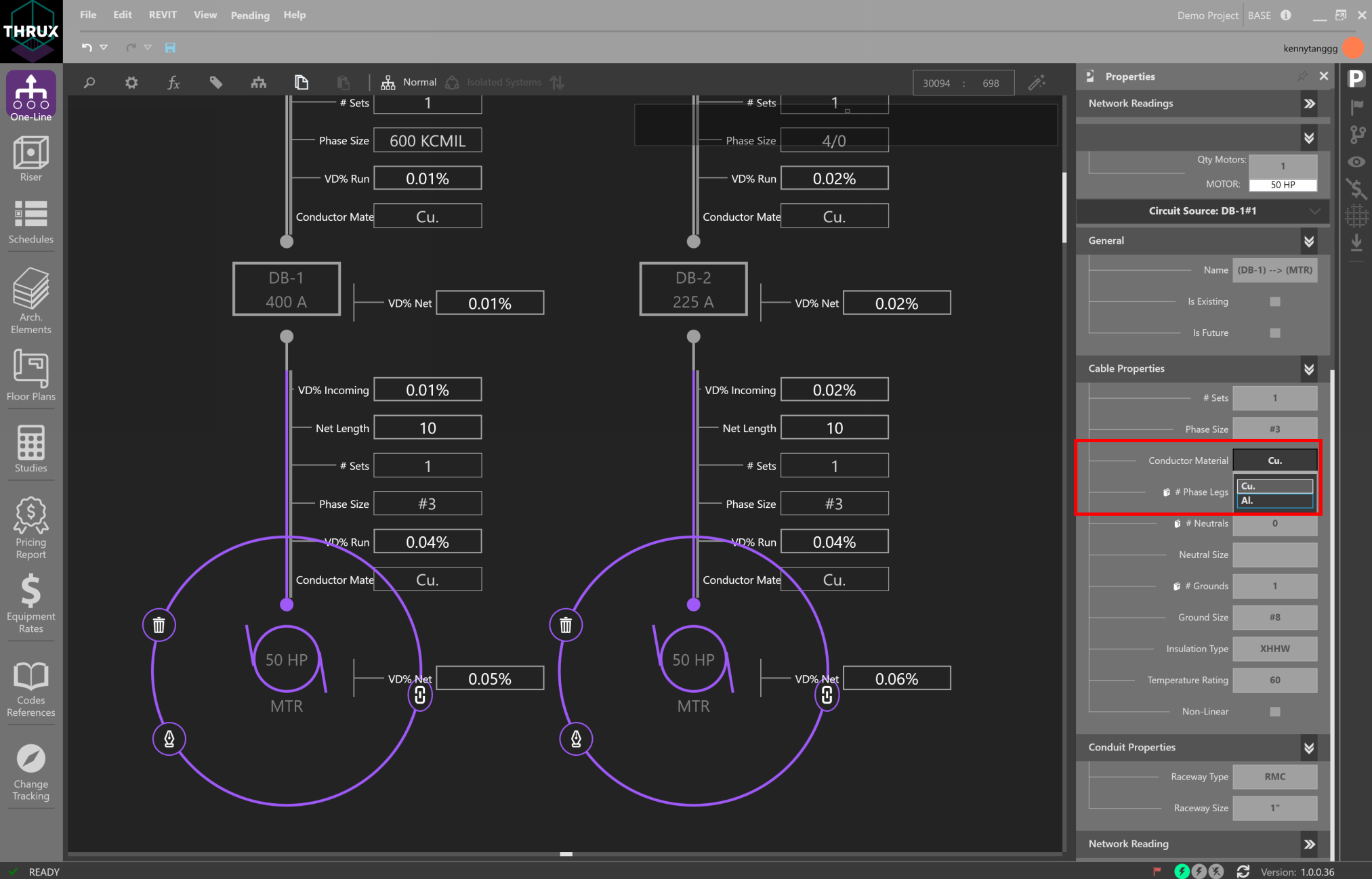
Note that since Design Assistance is on, the circuit’s code-minimum values are recalculated.
Reset to Code Minimum
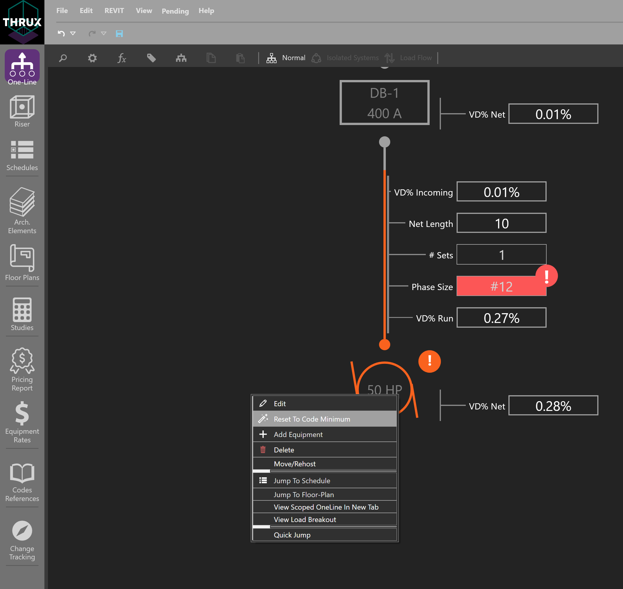
It is possible to manually modify circuit elements which cause a violation of safety codes and standards.
To recalculate or reset the values of a circuit to code-minimum values, right-click on an Equipment and use Reset to Code Minimum.
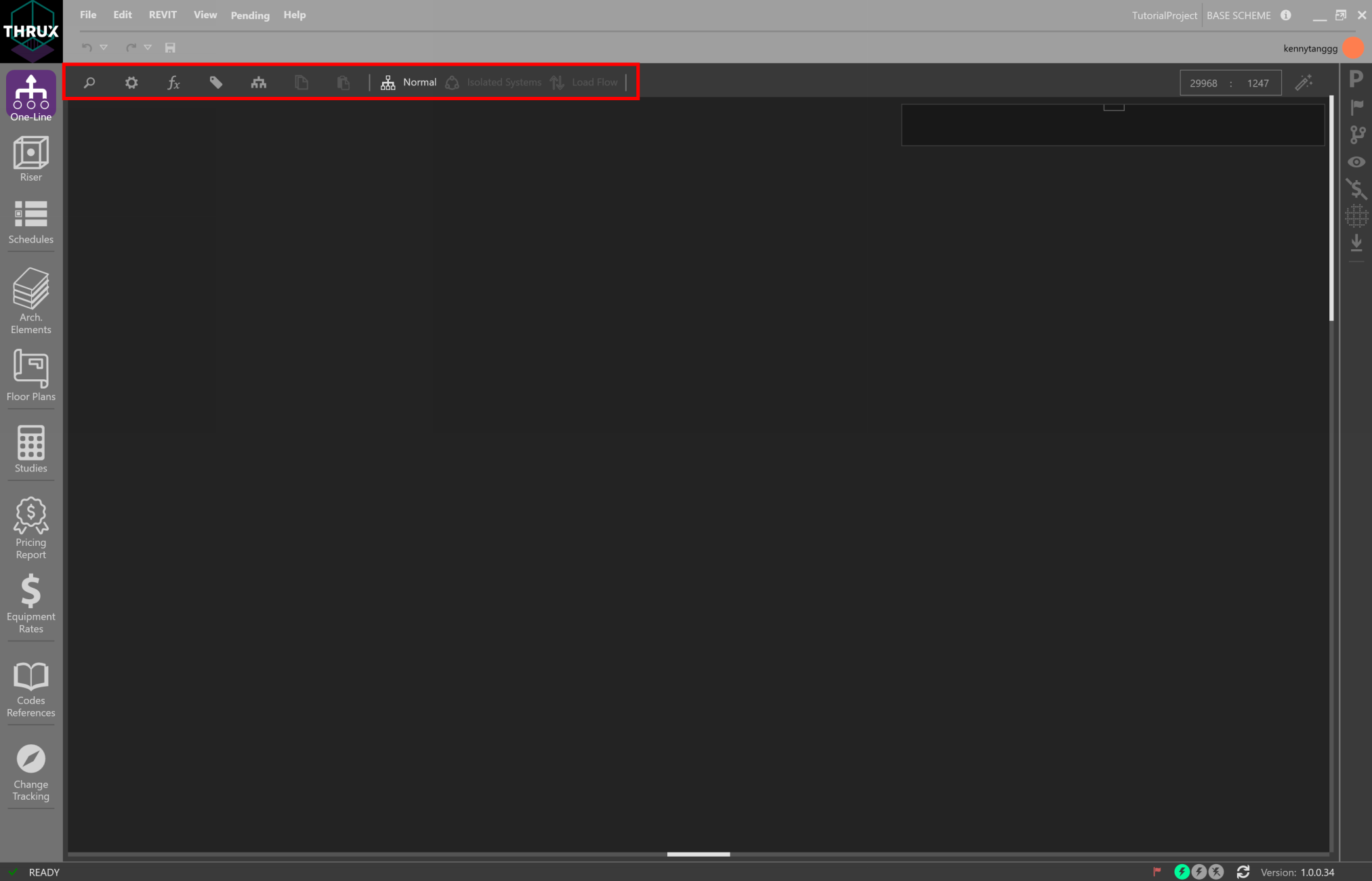
Workspace Toolbox
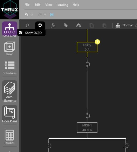
Utility functions like searching, additional viewing properties, or calculation settings can be found on the Workspace Toolbox on the top toolbar.
Searching
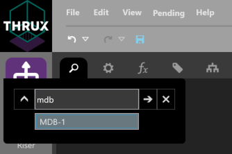
To search for Equipment, click the magnifying glass in the top left. Start to type the name of an Equipment. A dropdown will appear with any Equipment matching the specified name. Select the Equipment, and the Workspace will navigate to the associated Equipment.
Load Calculations
| Normal: | Calculations are based on the Net Load. |
|---|---|
| Board Capacity: | Calculations are based on 80% of the board’s Load Capacity. |
| Load Override: | Calculations are based on the Load Override value. For example, if a designer wants to model a specific loading scenario between points in a distribution system, enter these loading values into Load Override. |
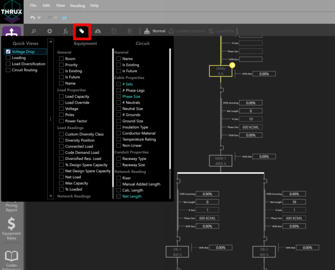
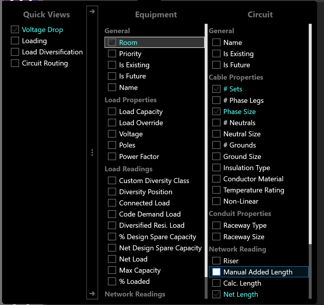
Property Tags/Quick Views
Property Tags can be applied to assist with design or network visualization. They give the designer flexibility with viewing specific properties of the model.
Click the tag symbol in the upper left of the Workspace Toolbox.
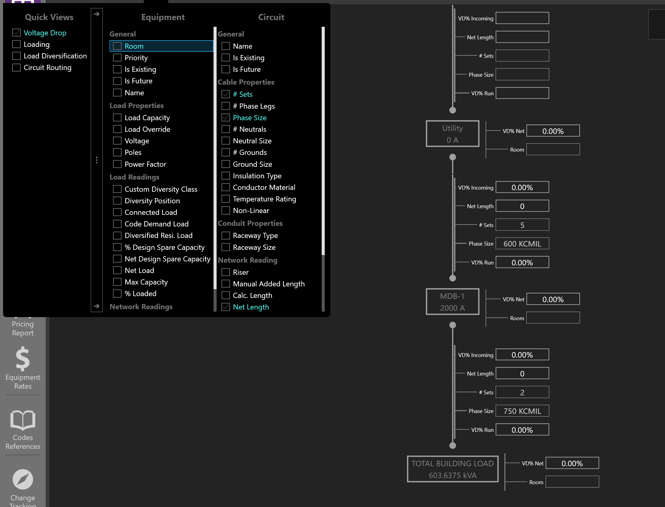
Quick Views are preset property groupings such as Voltage Drop, Loading, Load Diversification, and Circuit Routing.
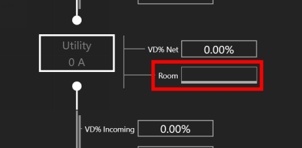
Assigning Room Locations
The distance between two pieces of Equipment are determined by their Room location via an orthogonal route. Open the Property Tags, and select Room.
Assign a Room by clicking in the textbox. If no Rooms are available, create them using the Architectural Workspaces.
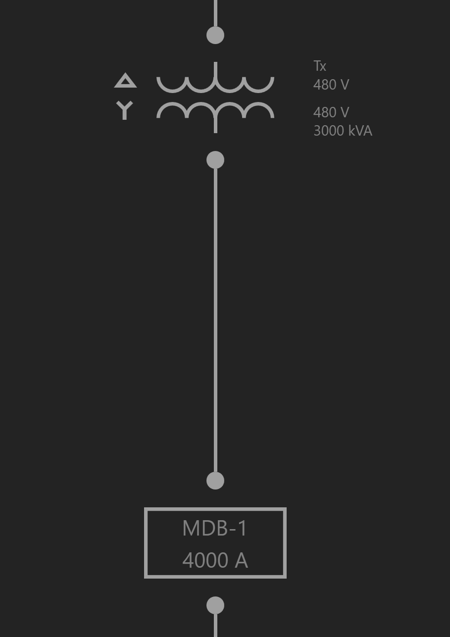
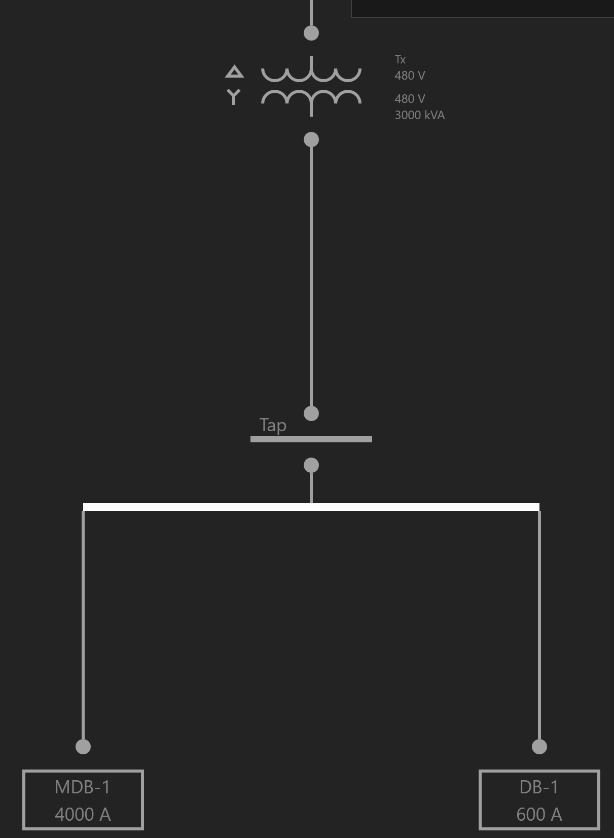
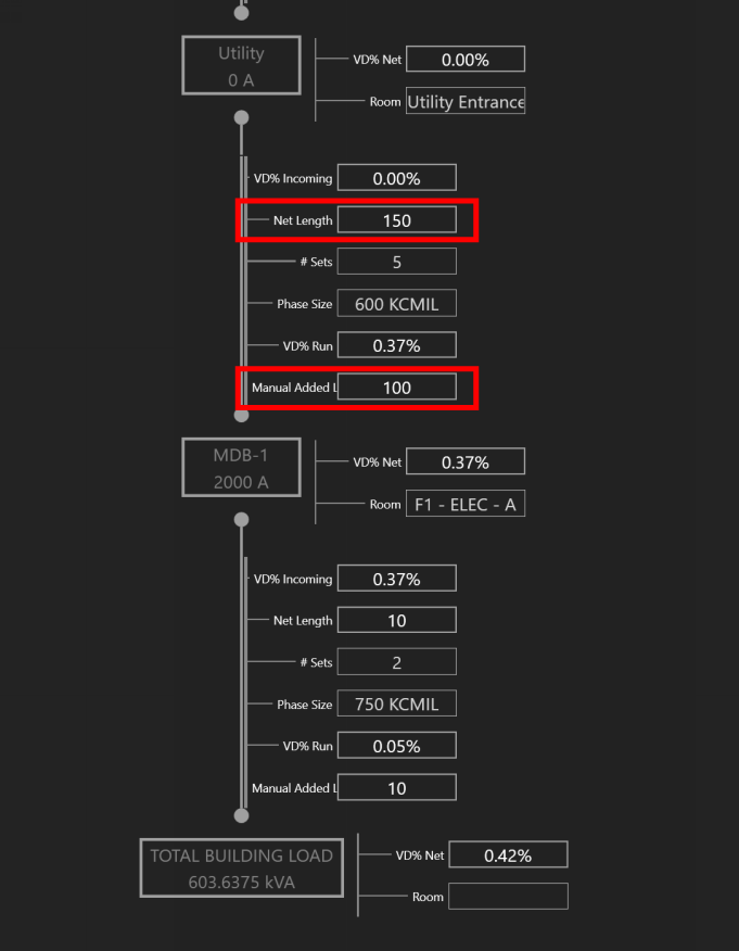
For the Distribution Board, MDB-1, note the Calc. Length before and after a Room location is assigned.
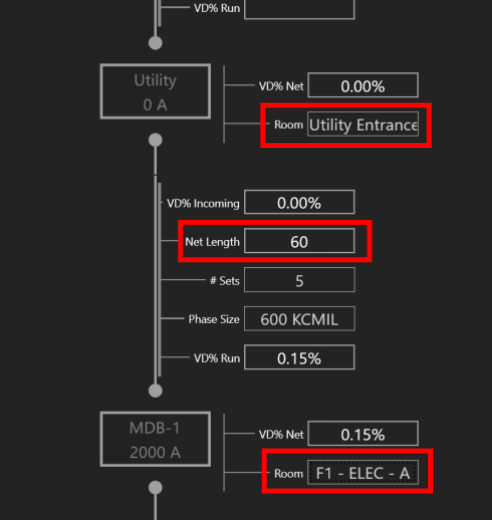
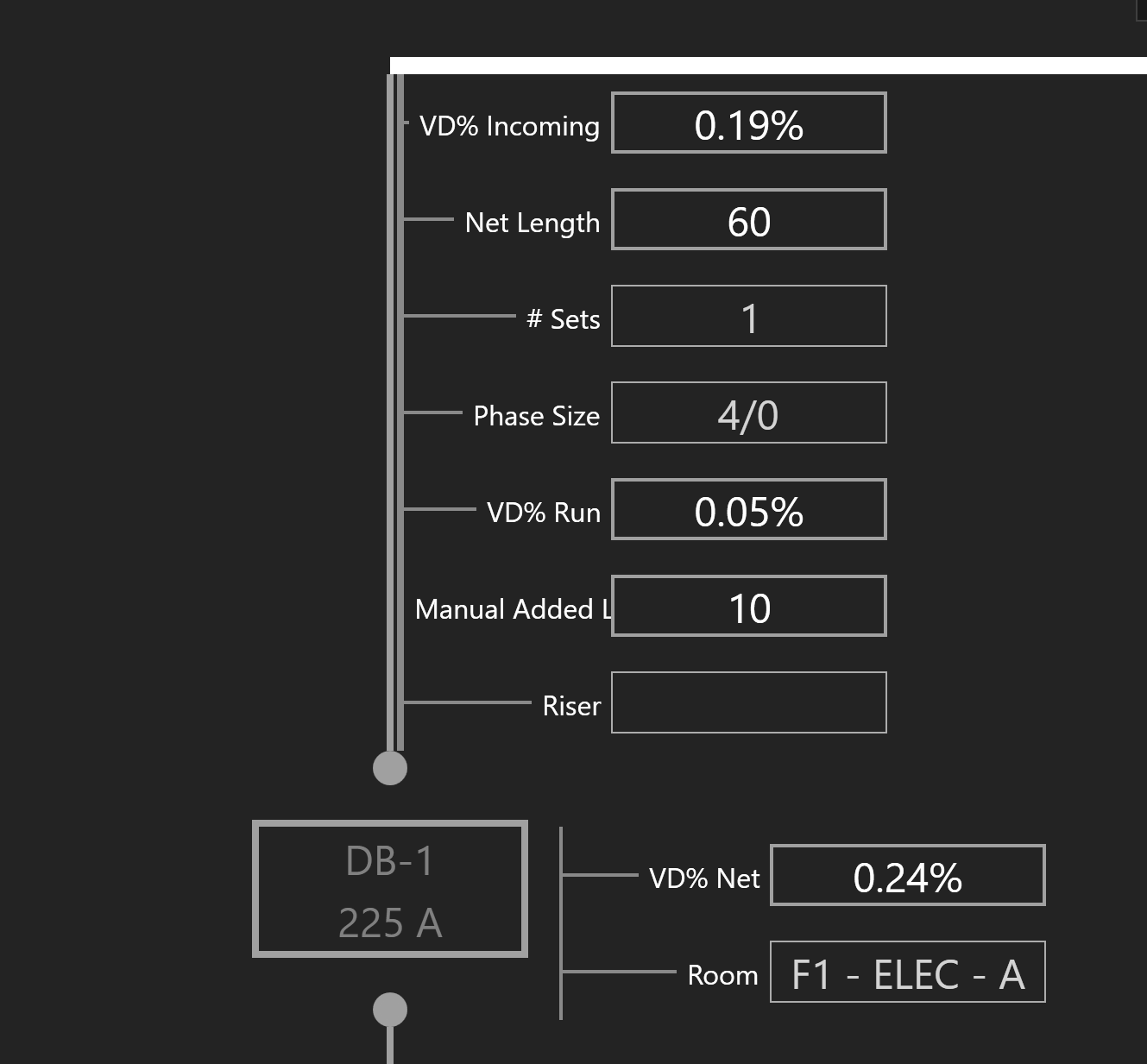
Calculated Length
Distances between Equipment are determined by their respective Room locations. Calc. Length represents the distance between two Rooms via an orthogonal route.
Manual Added Length
The distance between Equipment is defined as the Calc. Length. If a designer would like to account for additional length, change the Manual Added Length property.
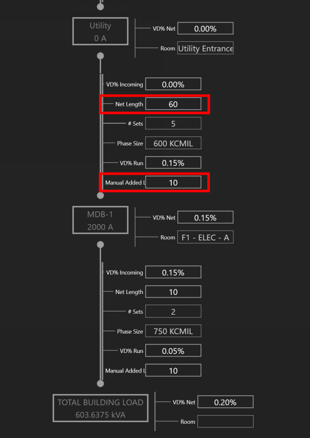
Note the Voltage Drop values as the length is changed.
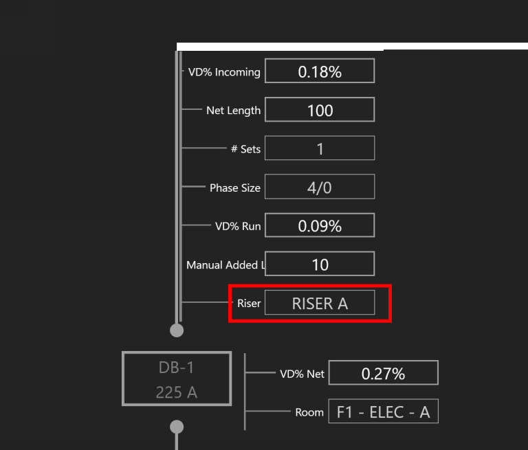
Routing Through a Riser
To route Equipment or to offset through a Riser, add the Riser Property Tag. Then select the Equipment to be routed through a Riser, and assign it a Riser.
Note the Net Length as the Equipment is routed through the Riser.
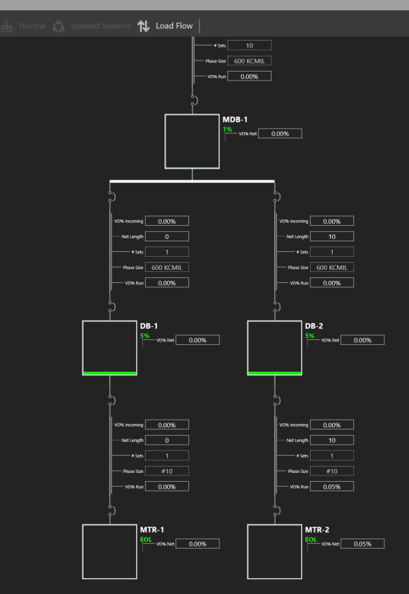
One-Line View Selectors
Different Views can be applied to aid the designer.
By default, Normal is selected.
Isolated Systems is recommended when viewing transfer switches. The designer can study voltage drop as a switch is fed from different sources.
Load Flow is recommended when studying how a system is loaded.
Creating a Transfer Switch
Transfer switches are connected to a primary and secondary source of power. To create a transfer switch, click Add Equipment and choose ATS/STS.
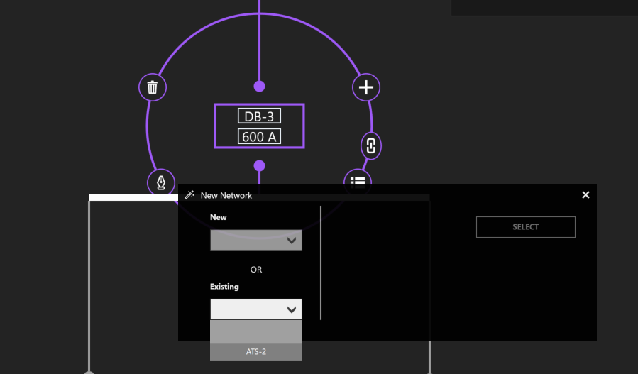
To connect the secondary source of power, choose another distribution Equipment. Then click Add Equipment and select an ATS/STS from the Existing dropdown menu.
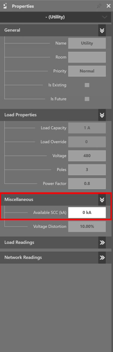
Short Circuit Current
Select the Utility source. Under the “Miscellaneous” property grouping, enter the value under Available SCC (kA).