Setup Wizard
Use the Setup Wizard on the right to start to create columns and Floors. Think of the combination of columns and Floors as a skeleton to base Equipment locations.
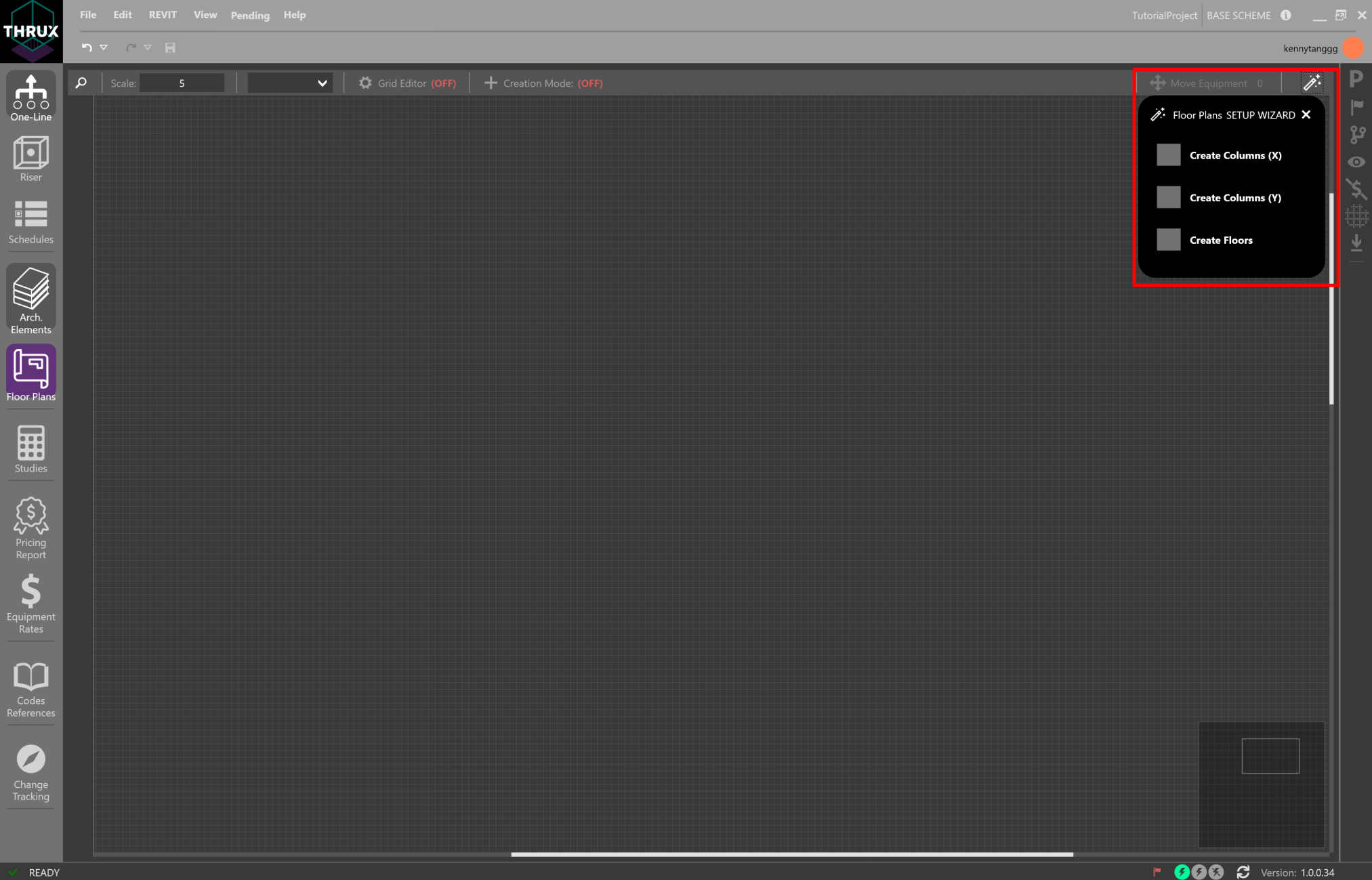
Select Create Columns to create multiple columns and Floors at a time by specifying a distance in between each. These can be individually modified in the Arch. Elements Workspace.

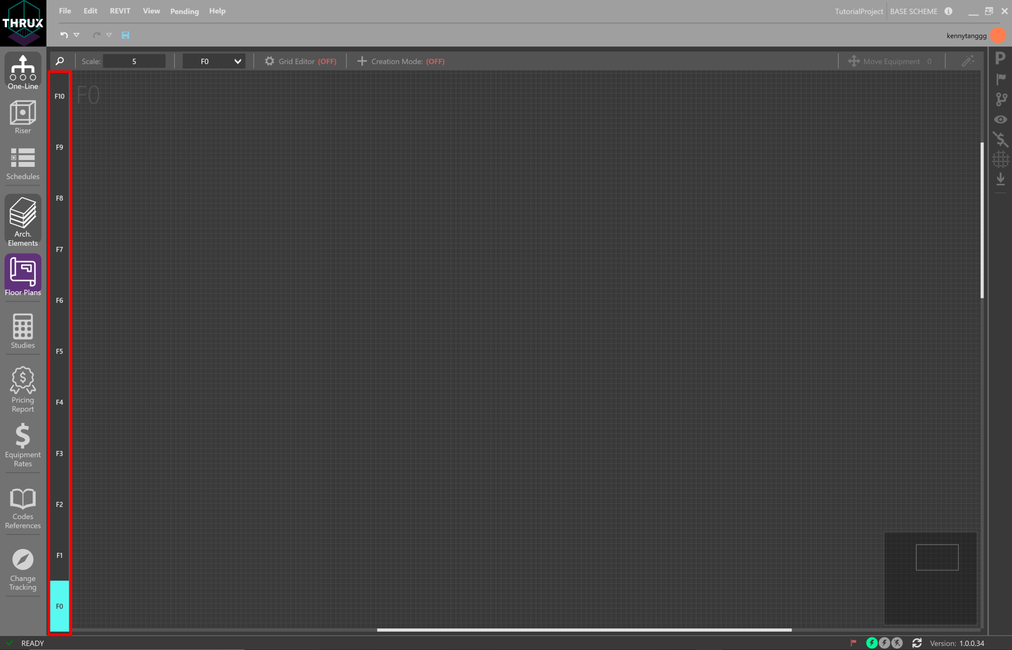
Cycle through Floors by selecting the Floor on the left sidebar. The selected Floor is highlighted in Cyan.

Creating Rooms
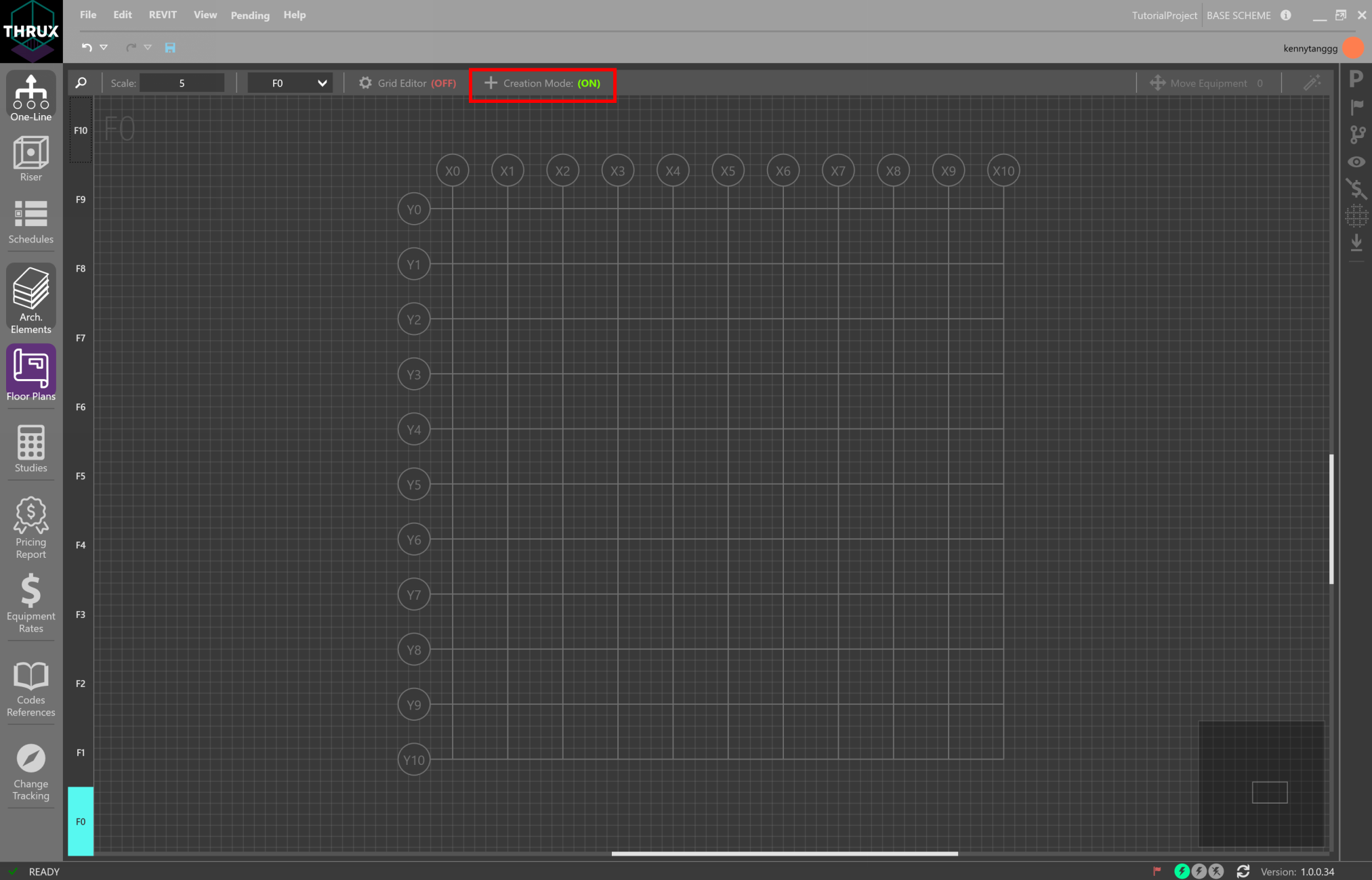
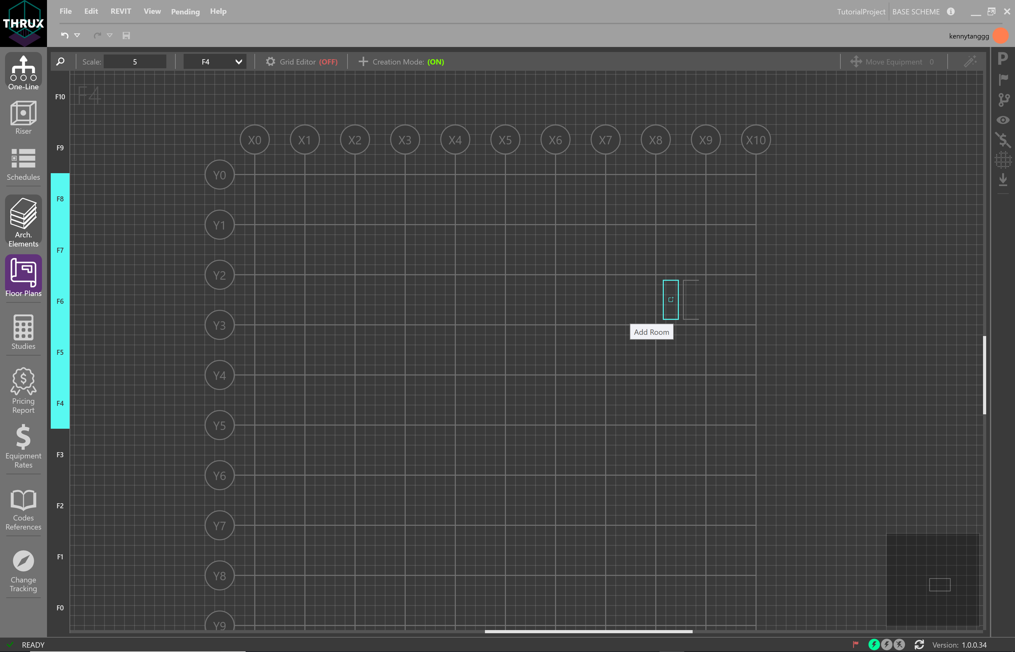
Once Floors are created, enable Creation Mode. This allows the designer to create Rooms and Risers.
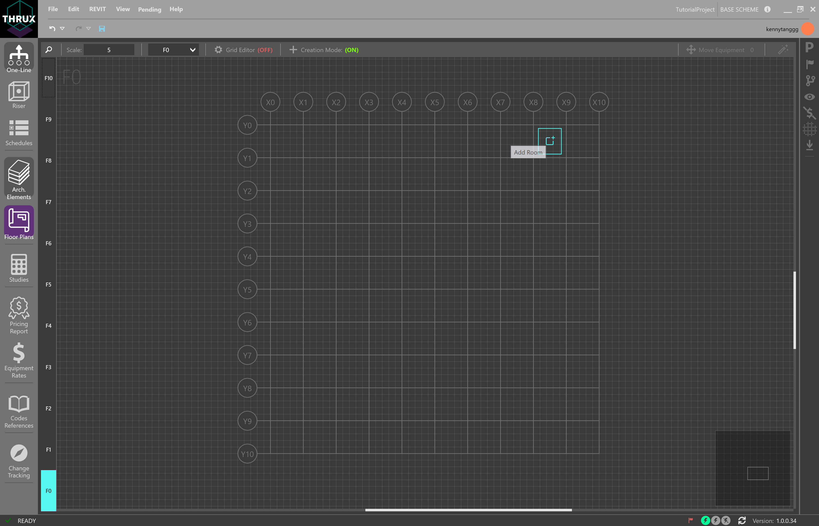
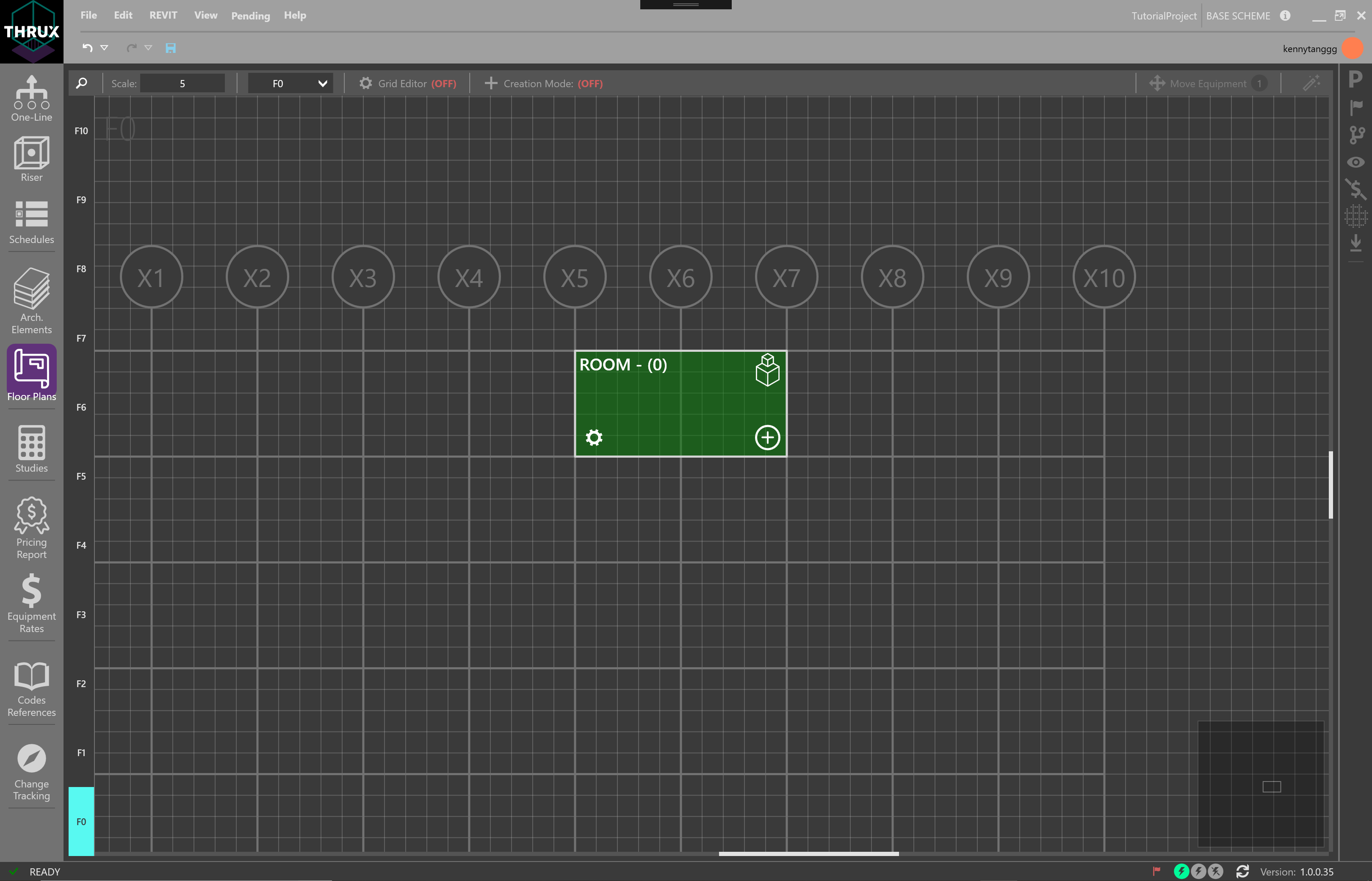
Create a Room by hovering the mouse between column regions and clicking Add Room.
To create a Room in a common location spanning multiple Floors, use Shift+Click to select multiple Floors on the left sidebar and then hover over a grid region to click Add Room.
Risers
Risers are shafts or spaces that are designated for groups of pipes to route to and from distribution equipment.
Therefore, instead of routing directly from a distribution equipment to a load, the route can offset through a riser shaft before terminating at the load.
To create a Riser, in the Floor Plans Workspace, select a group of Floors that the Riser will span. Use Shift+Click to multi-select. Then hover over a grid region and select Add Riser. Risers can also be modified in Architectural Elements.

Moving Rooms/Risers
Once Rooms or Risers are created, move a Room or Riser by clicking and dragging it to the new region. The selection will highlight green. Note that Creation Mode must be off.
Conduit Lengths
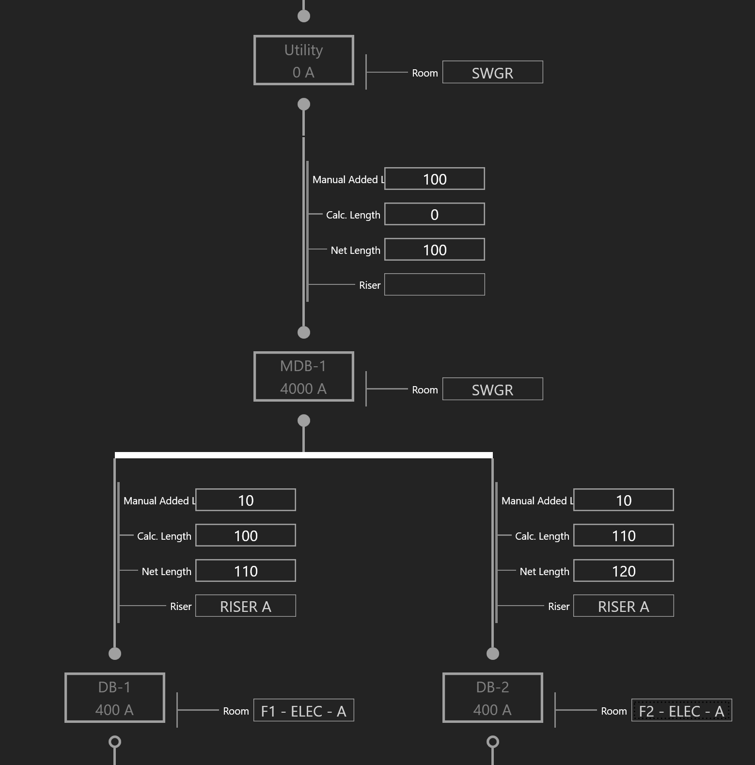
Conduit lengths are determined by a starting location and an ending location.
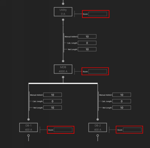
The Calculated Length is the distance between two pieces of Equipment which is the orthogonal route determined by their Room locations. Modify the Manual Added Length to account for an additional routing distance of the run.

In addition, if the conduits are being routed through a riser shaft, assign a Riser to the terminating equipment. Note how the Calculated Length and Net Length of the circuit change.
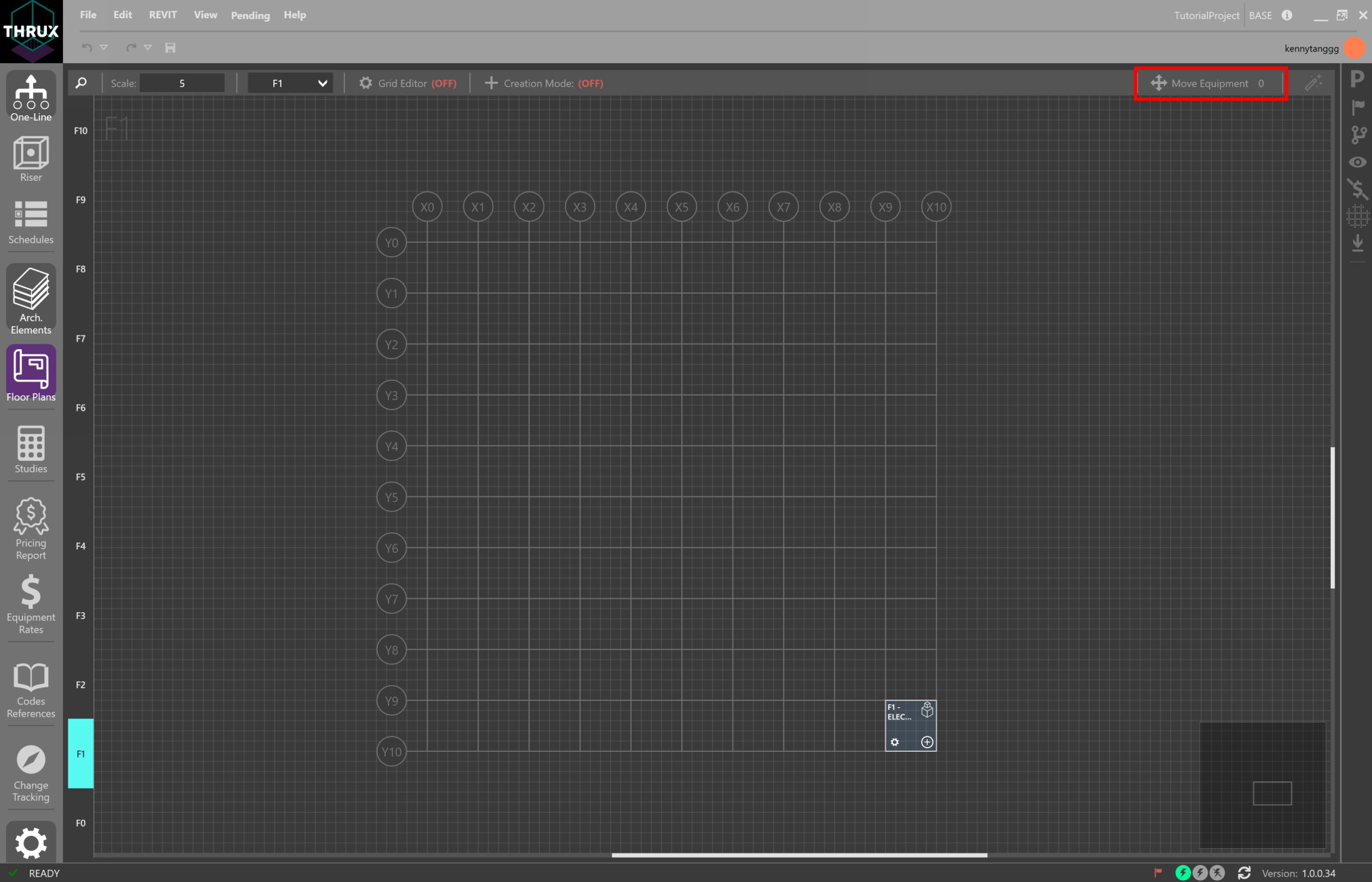
Move Equipment
Designers often need to change the locations of Equipment. Move Equipment is intended to quickly place Equipment in Rooms.
There are two collections of Equipment: Orphaned Equipment and Hosted Equipment. An Orphaned Equipment does not have a Room assigned to it. A Hosted Equipment has a Room assigned to it.
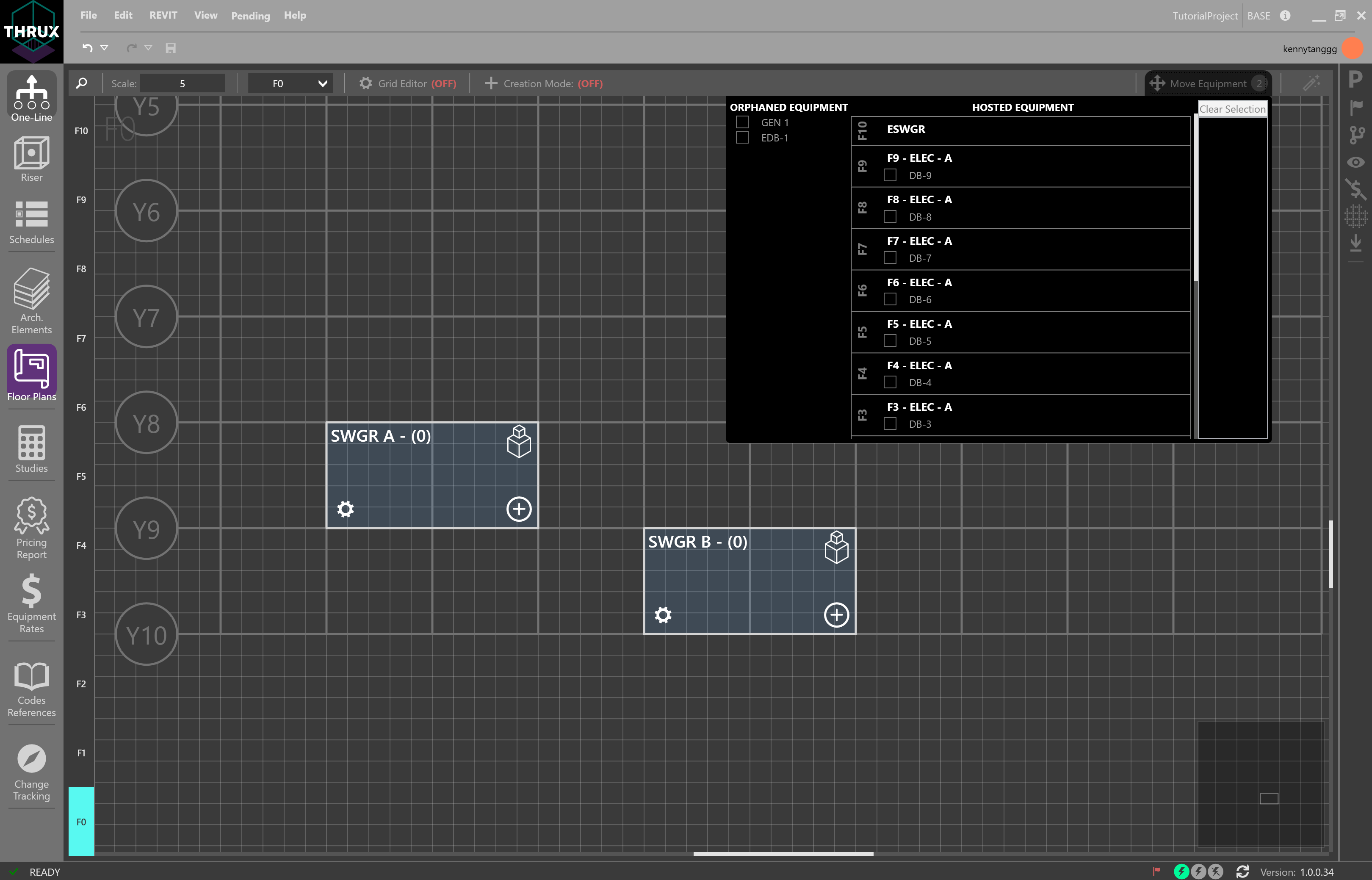
Select the Equipment. Rooms and Floors will be highlighted in purple.
Hover over a Room and click the Move/Add icon.
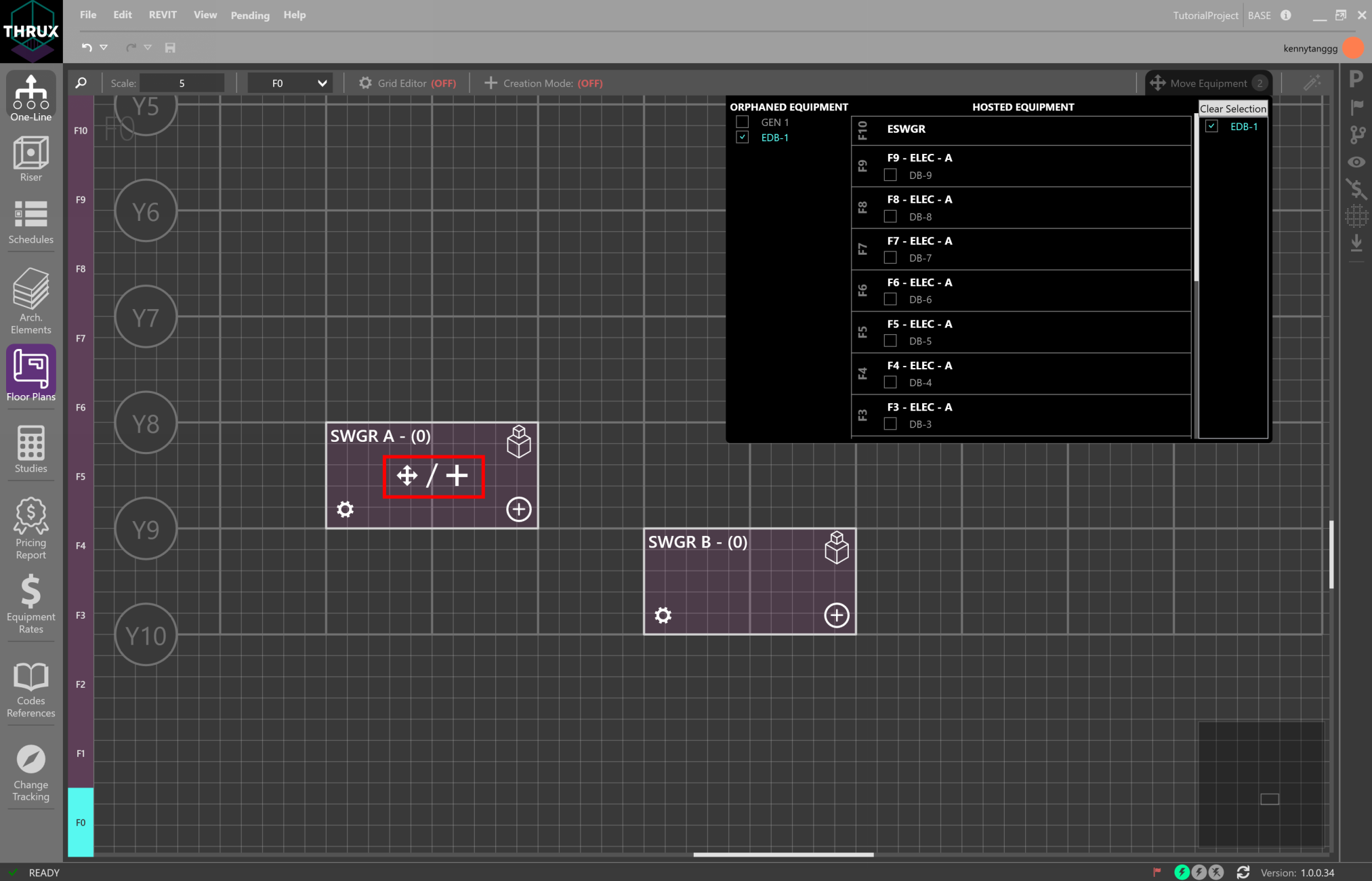
The Room indicator will notify the designer when the Equipment is added.
