Navigating THRUX
Workspace Toolbar
The left-side toolbar is the Workspace Toolbar. The purple shading indicates an open and active Workspace, while grey shading only indicates an open Workspace.
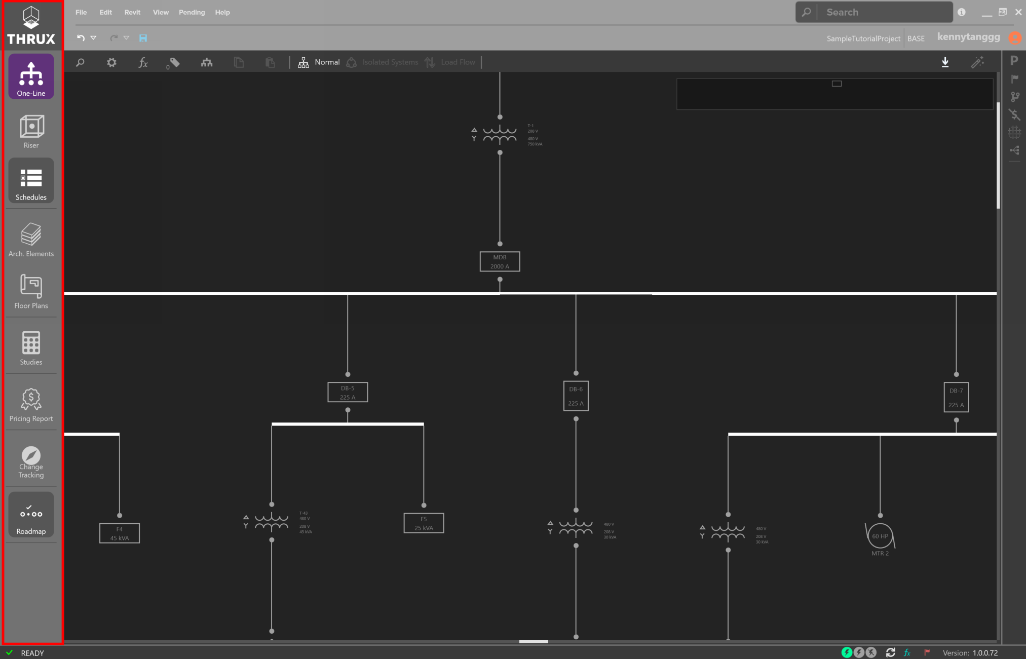
Workspace Toolbar
Workspaces can be detached to separate windows by clicking and dragging the Workspace’s icon in the Workspace toolbar.
These windows can be docked by clicking Dock in the top right of the undocked window.
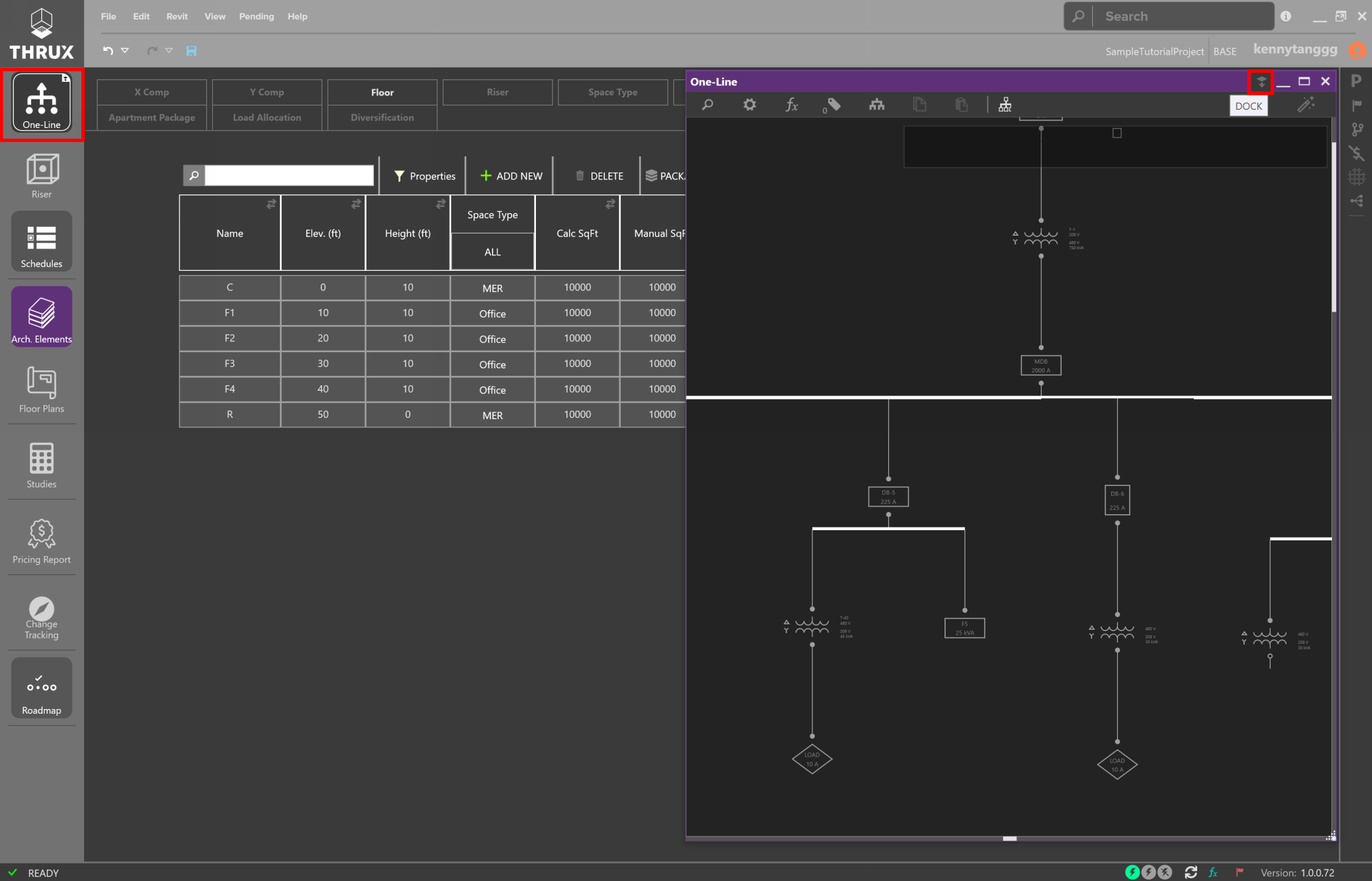
Docked One-Line separate from the main application
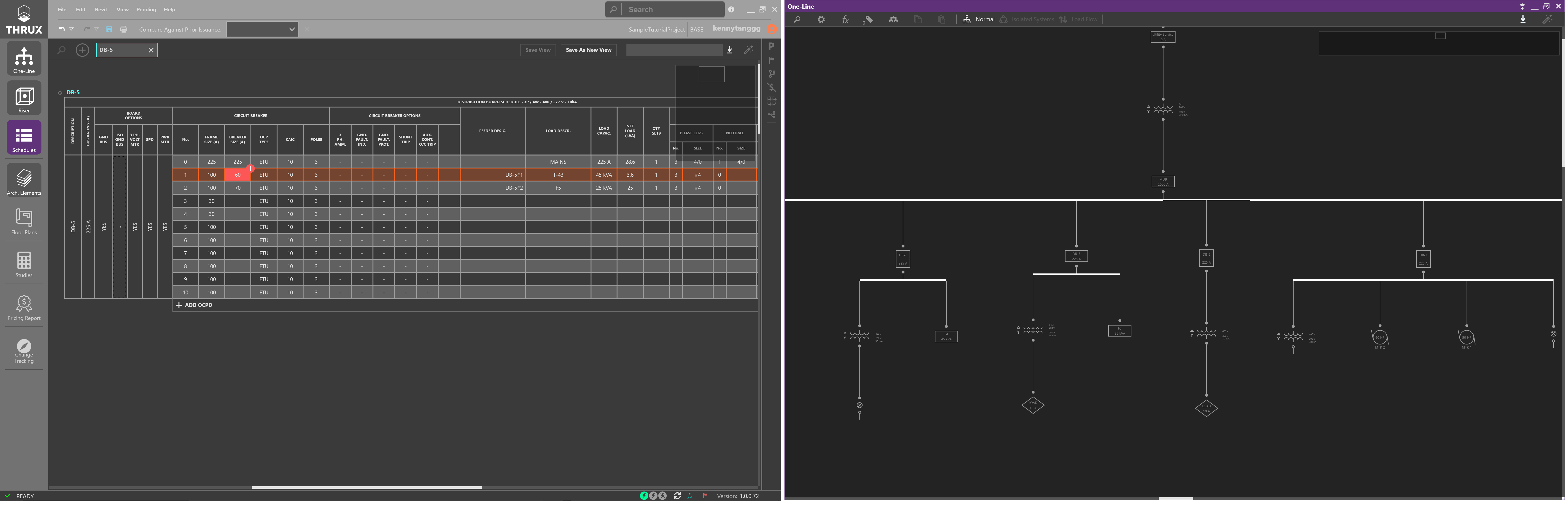
Docking Workspaces allows Workspaces to be viewed on multiple monitors
Explorer Toolbar
Explorers and other Utility tools can be found on the Explorer Toolbar on the right-side toolbar. These tools can be pinned to always be visible (pin icon).
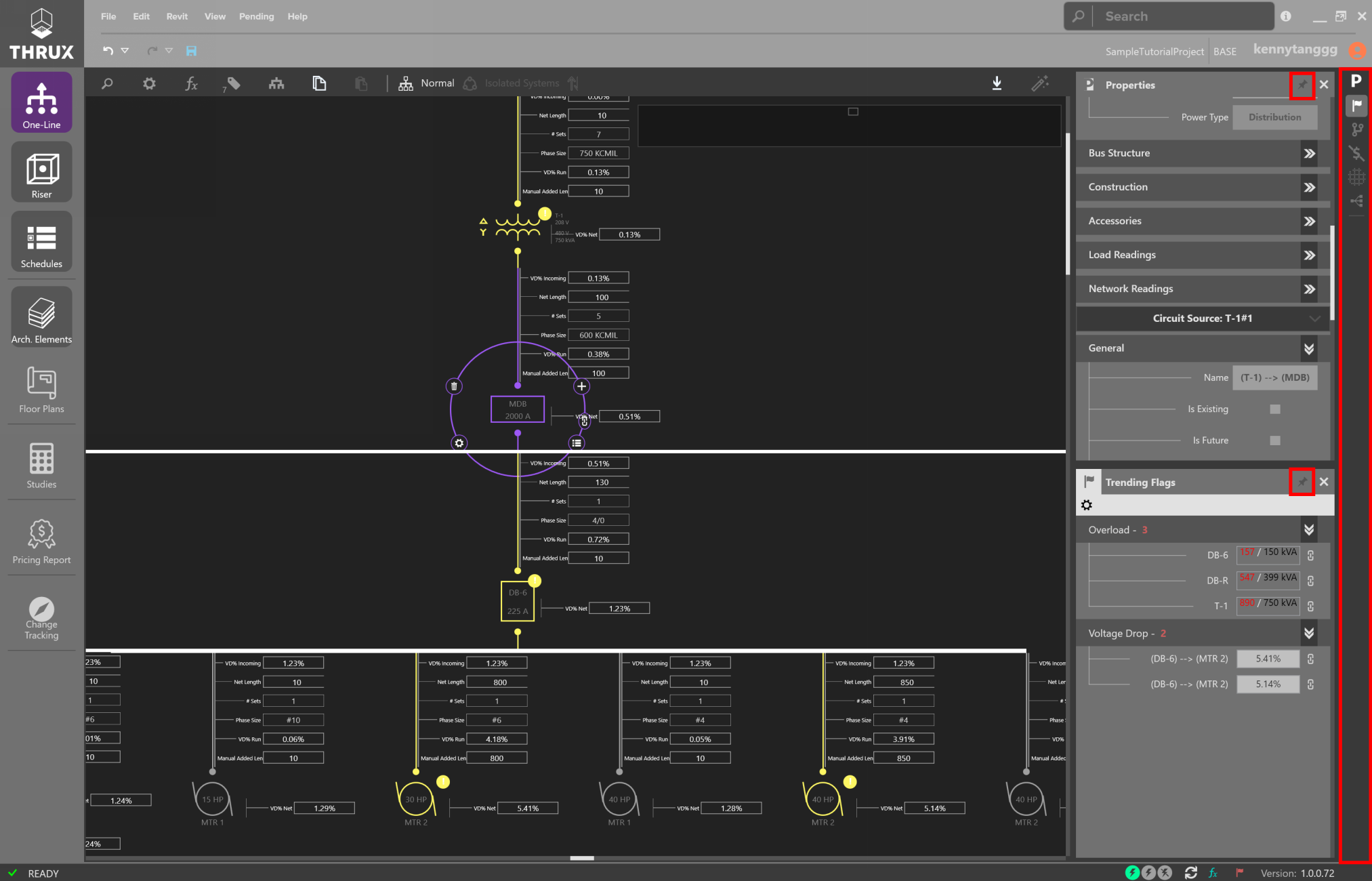
Using the Properties Explorer and Flag Tracker while working in the One-Line Workspace
Navigation Bar
Designers have the ability to search for anything within the model.
For example, if searching for a piece of Equipment, simply type the name.
Options will be displayed where something is found.
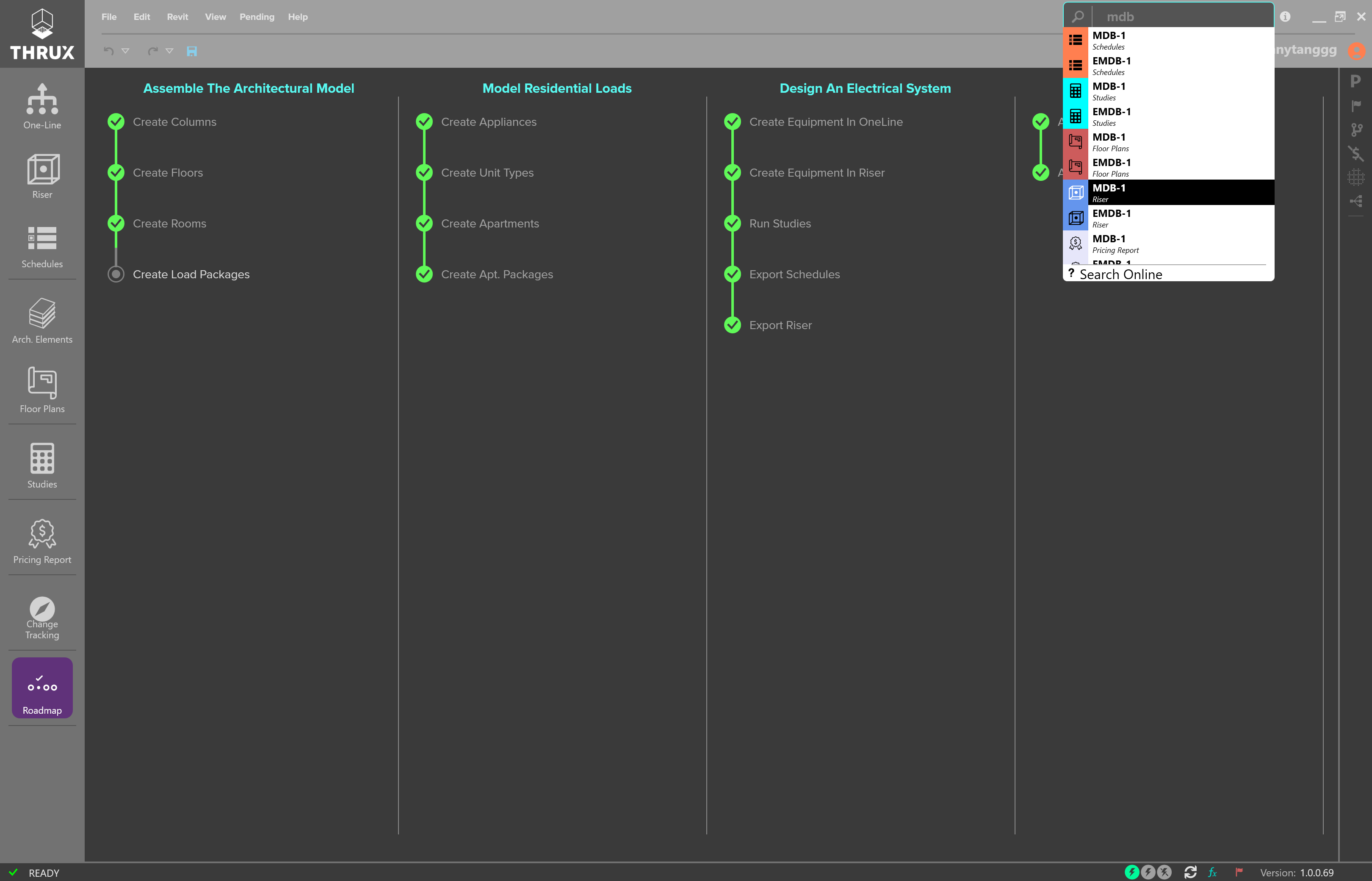
Navigation Bar
Selection will navigate you to the location within the application.
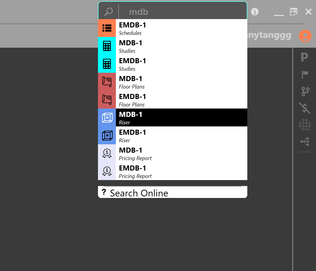
Navigating to the Schedule for MDB-1
Additional Commands
Zoom Extents allows the user to quickly pan to the center of the screen. Double click the mouse wheel to Zoom Extents.
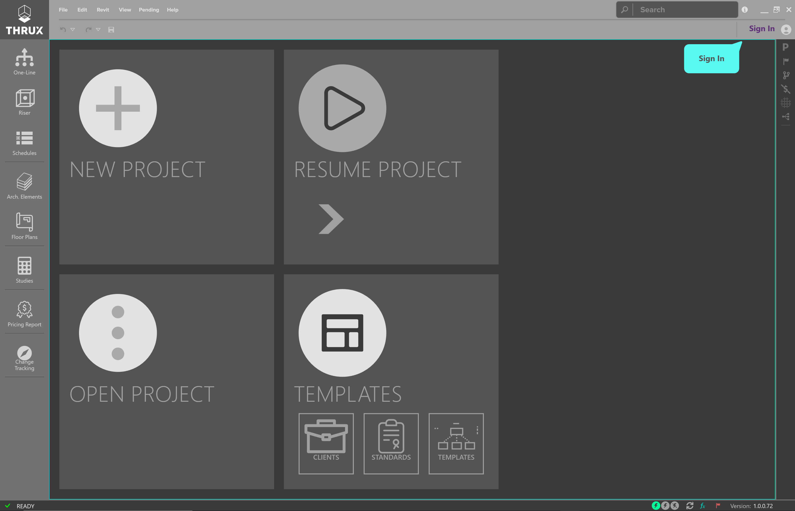
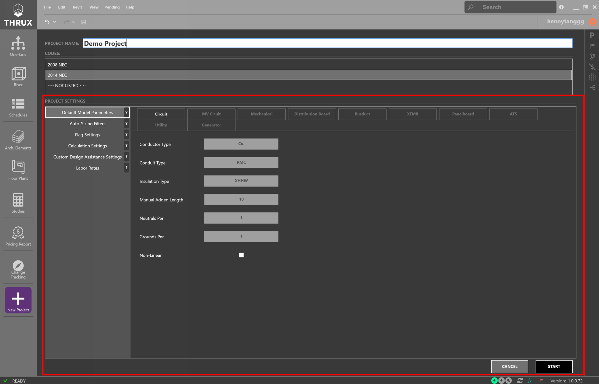
Creating a New Project
Click the Home button, and then the Add (+) button to create a new Project.
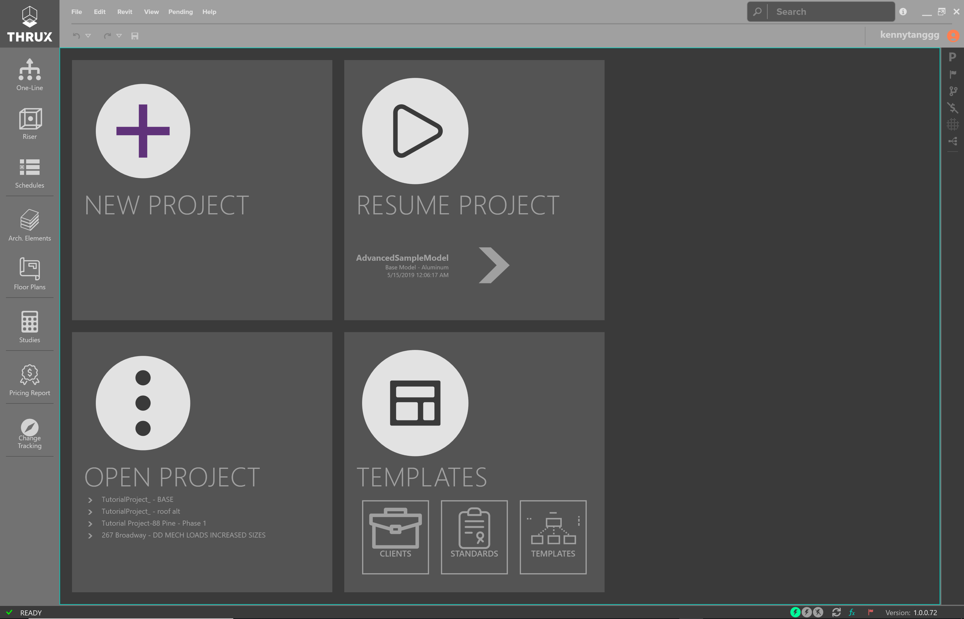
The Home Screen is a Project portal that provides quick access to recent Projects
Opening an Existing Project
Existing projects or recently opened projects are shown below the Open Project section.
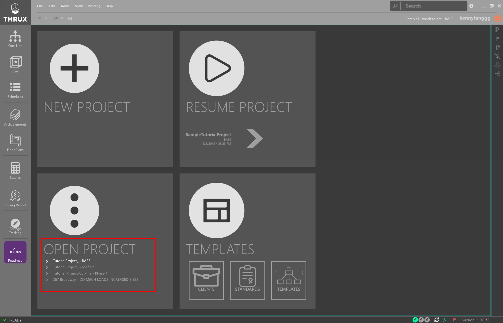
Check the recently opened lists to pick up where you left off
Defining Architectural Elements
Overview
The goal of the Architectural Workspaces, Floor Plans and Arch. Elements, is to provide a way for you to quickly mass the load of a building. These locations aid with point-to-point calculations such as voltage drop.
However, these Workspaces are completely optional. For a smaller project, you may not find it necessary to set up these Workspaces and instead, find it faster to manually input feeder lengths in the One-Line.
This information can be imported from an Architectural Revit model.
The Arch. Elements Workspace allows you to modify the architectural elements of the model. Here, it is possible to modify other characteristics of a Floor. For example, when massing the load of a building, you may want to assign a load requirement or load density to each Floor. This load is based off of the Floor’s Space Type.
These elements can be created in the Floor Plans Workspace, or the Architectural Elements Workspace.
Equipment Distances
Calculated Length
Distances between Equipment are determined by their respective Room locations. Calc. Length (Calculated) represents the distance between two Rooms via an orthogonal route.
The vertical distance between Rooms is the difference between their respective elevations.
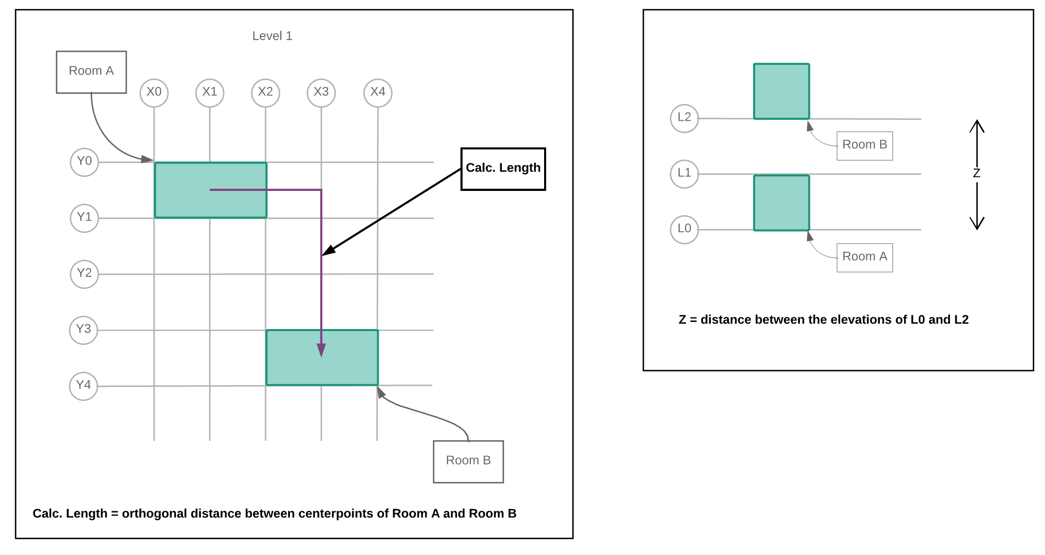
Route between Rooms on the same Floor, and vertical distance between stacked Rooms
It is often necessary to offset through a Riser. The total distance or Net Length is determined by the centerpoints of the respective entities.
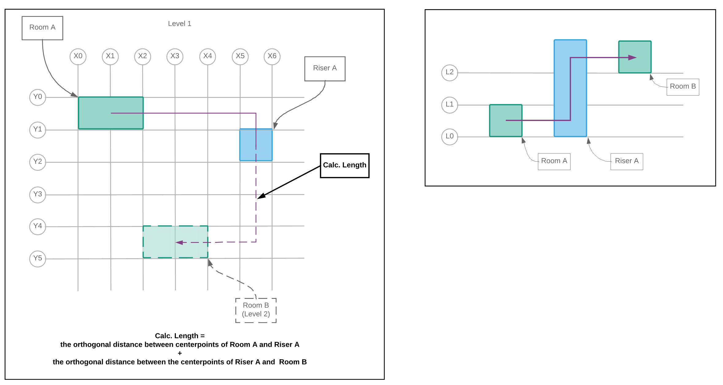
Routing from Room A, through Riser A, and terminating at Room B
Manual Added Length
Manual Added Length is an additional factor which is added to a circuit’s Calc. Length property and is a customizable default setting. See here for more information.
Net Length
The Net Length is composed of the Calc. Length and the Manual Added Length.
Loading System
The Architectural Elements are the unifying components which Engineers base their design. However, various engineering disciplines refine and base their calculations off of different elements.
You have the ability to abstract the architectural elements of a model to create Load Packages. Ideally these entities would be abstracted away from a Revit model. However, during the early stages of development, a Revit model may not exist.
Creation of these architectural entities allow for the THRUX engine to fully utilize its Loading System which applies loading factors dictated by the designer and the Project’s applicable safety codes and standards.
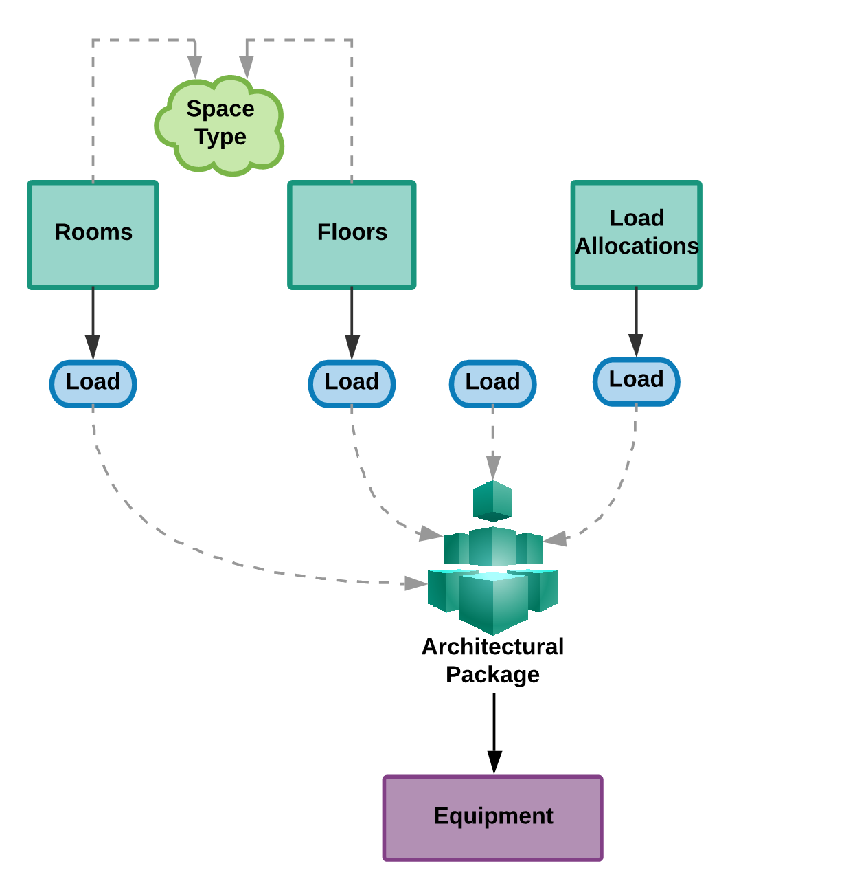
Creating Architectural Packages to model loads
Modeling residential loads relies on creating entities that are based off of the NEC.
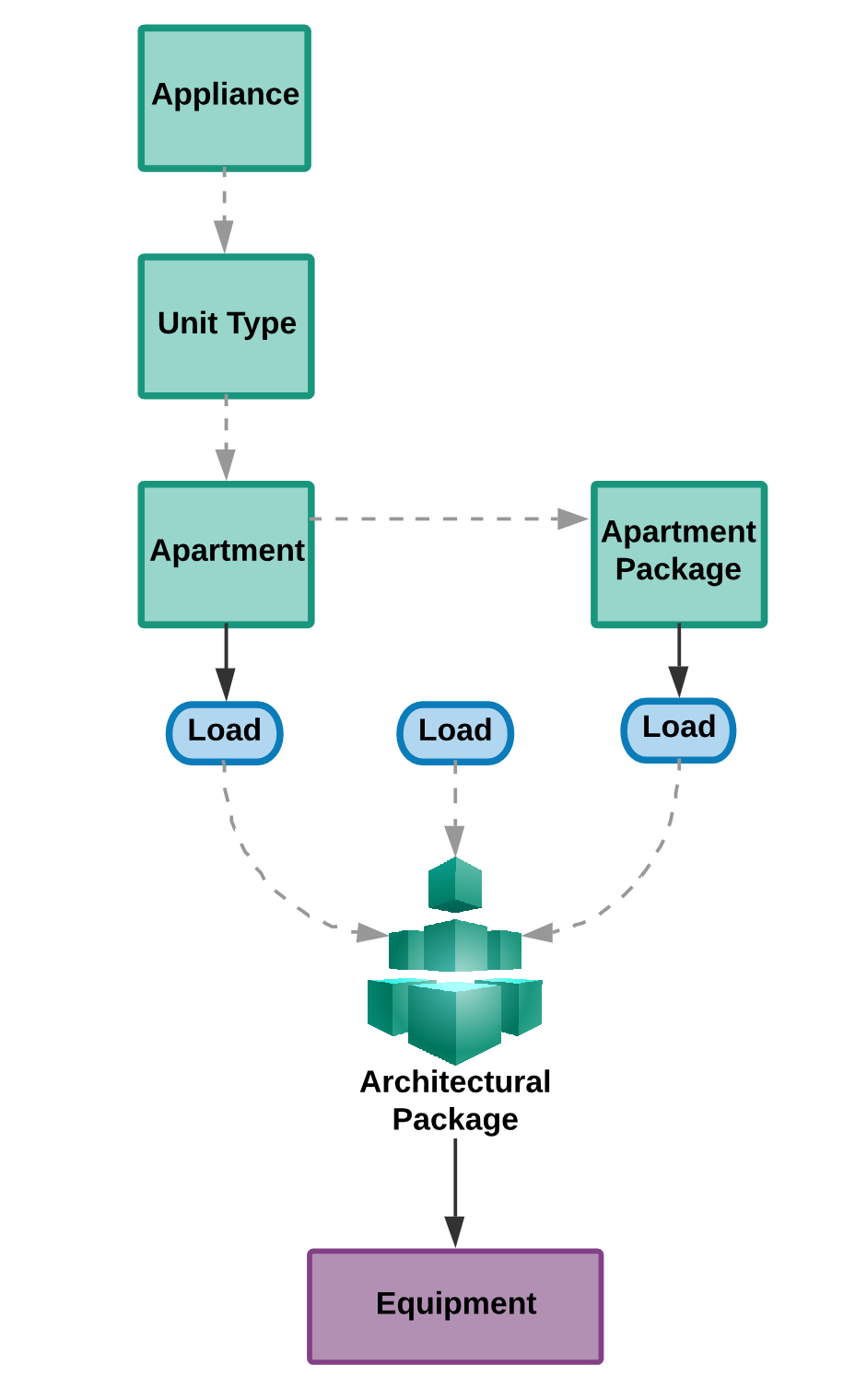
Creating Architectural Packages to model residential loads
Groups of architectural entities can be created within THRUX, or imported from a Revit model. Ultimately, Architectural Packages are loads that can be attached to Equipment.
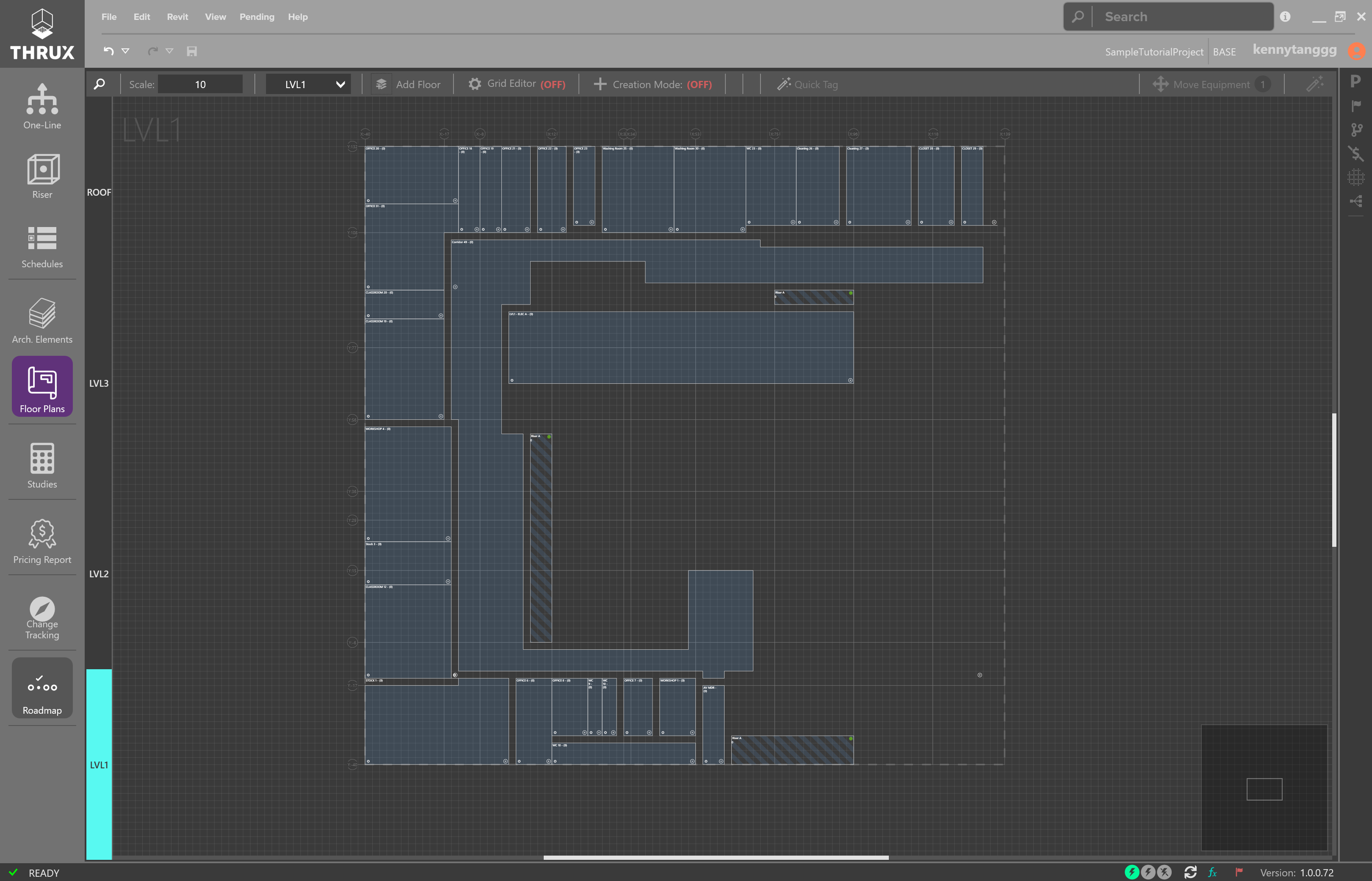
Floor Plans
The Floor Plans Workspace is a 2-D representation of the Project and is used to model locations of Equipment.
Architectural Elements
Arch. Elements are a tabular representation of the Architectural entities of the model.
Building the Electrical Model
Overview
There are three (3) main Workspaces to build the electrical system.
These include: Riser, One-Line, Schedules.
Reports of a model can be generated at any time using the Studies Workspace.
Hosted vs. Unhosted Systems
If a piece of Equipment is not fed from a source, then it is designated as Unhosted. During the stages of design, it is common to model hypothetical scenarios before all information is known. For example, as part of a larger project, an Architect may decide to create a space dedicated for a computer lab, but not yet decide on its exact location. While the location is not yet finalized, you can still model an Unhosted System with the intent of attaching the system to the main network in the future. Modeling Unhosted Systems allows flexibility when the source of a network is not yet known or if you want to create segregated distribution networks and tie them together at a later time.
Riser
One-Line
Schedules
- Open Schedule
- Adding, Deleting, Editing Equipment
- Copy/Paste Circuits
- Select All
- Reset to Code Minimum
- Moving, Rehosting Equipment, or Reordering Circuits
- Lock/Unlock
- Adding OCPD’s
- Navigate
- Comparing Schedules Between Branches
- MLO - Main Lug Only
- Configure as Tap
- Converting Breaker/Switch and Fuse
- Multi-Pole Circuits
- Poles
- Schedule Views
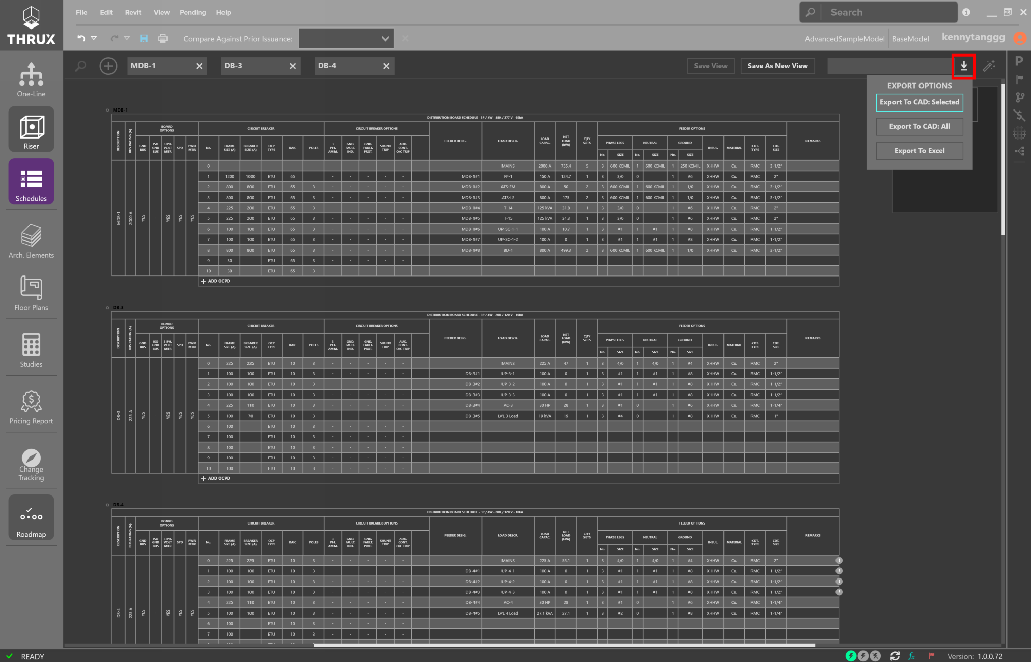
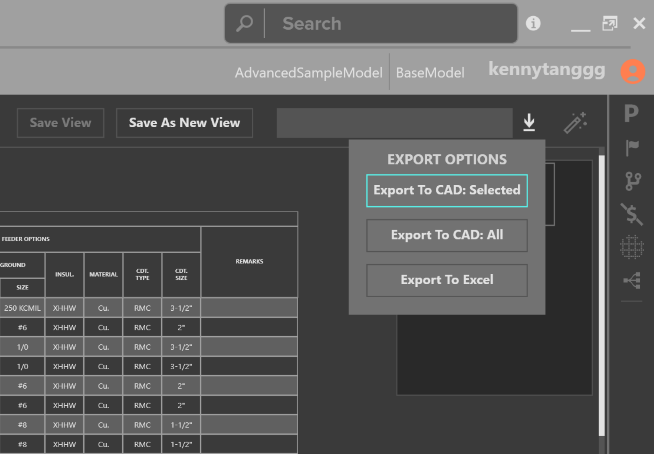
- Exporting
Flag Tracker
Pricing Model
The Pricing Model is built around the Electrical model and can be viewed in a few Workspaces. The Price Tracker is used to live monitor the price of the model. For example, as you change the location of a major equipment room, the Price Tracker would display order of magnitude estimates for that change. For a more complete tabular report, use the Pricing Report Workspace.
Equipment Rates is a customizable catalog which composes the bid for materials.
Project Management
Engineers are often tasked to study different alternatives or schemes and present them to the Owner.
The Issuance Log allows you to create Branches, while the Change Tracking Workspace allows you to compare Branches against the base Branch.
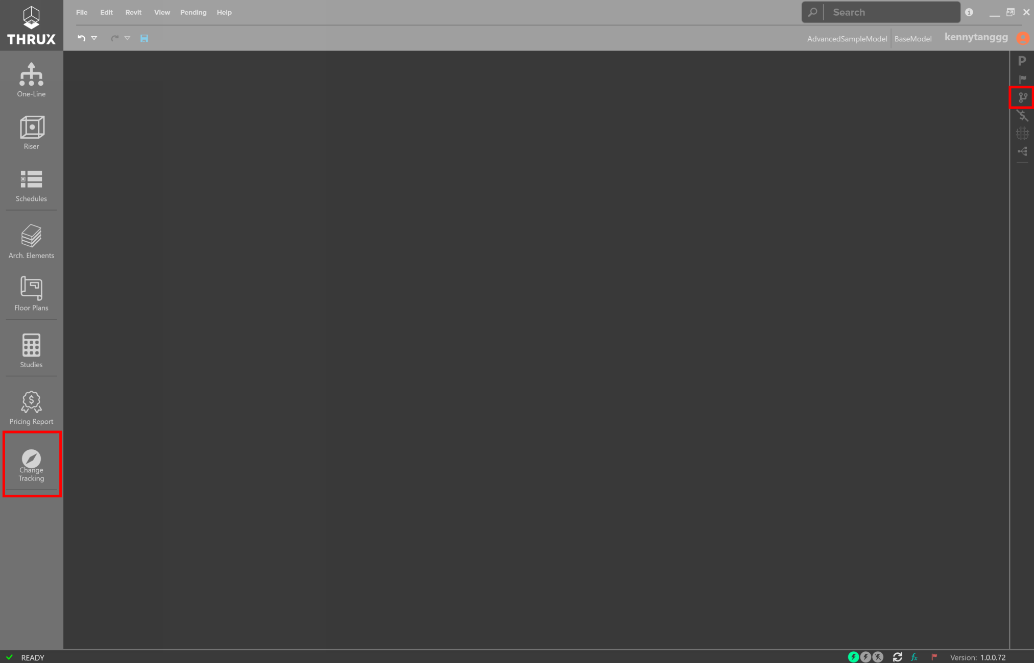
Project Management tools - Issuance Log, Change Tracking
Explorers and other Utility Tools
The right-side toolbar of THRUX is generally where the explorers or utility tools are located. Explorers can be pinned to always be visible while other explorers are being used.
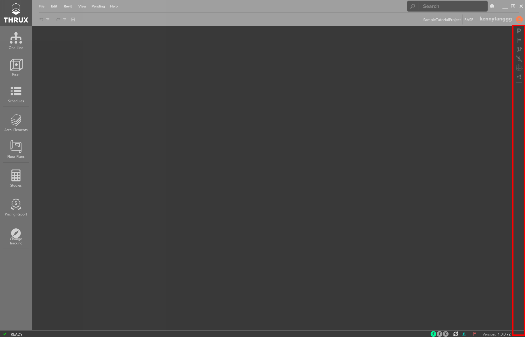
Explorer Toolbar
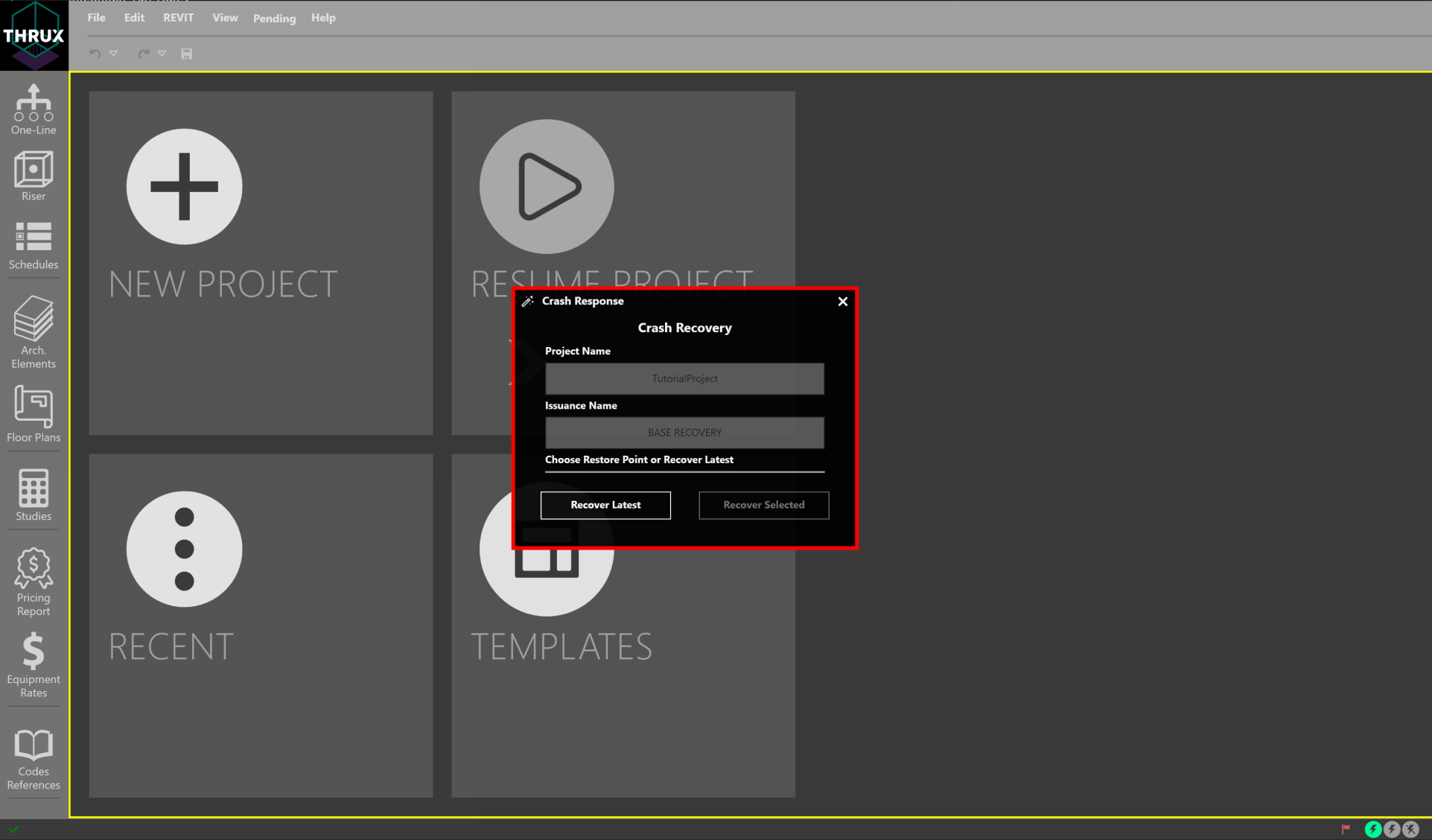
Recovery Options
THRUX models are stored in the cloud and are periodically backed up. If THRUX crashes, reopen THRUX. A recovery window will prompt to restore to the latest restore point, or an earlier restore point.
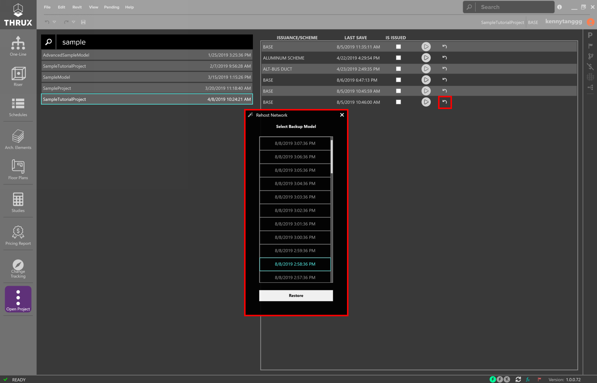
Another option is to restore a model to a restore point via the Open Project window. Use the Restore button (restore icon) and then choose a restore point.
Automatic Updates
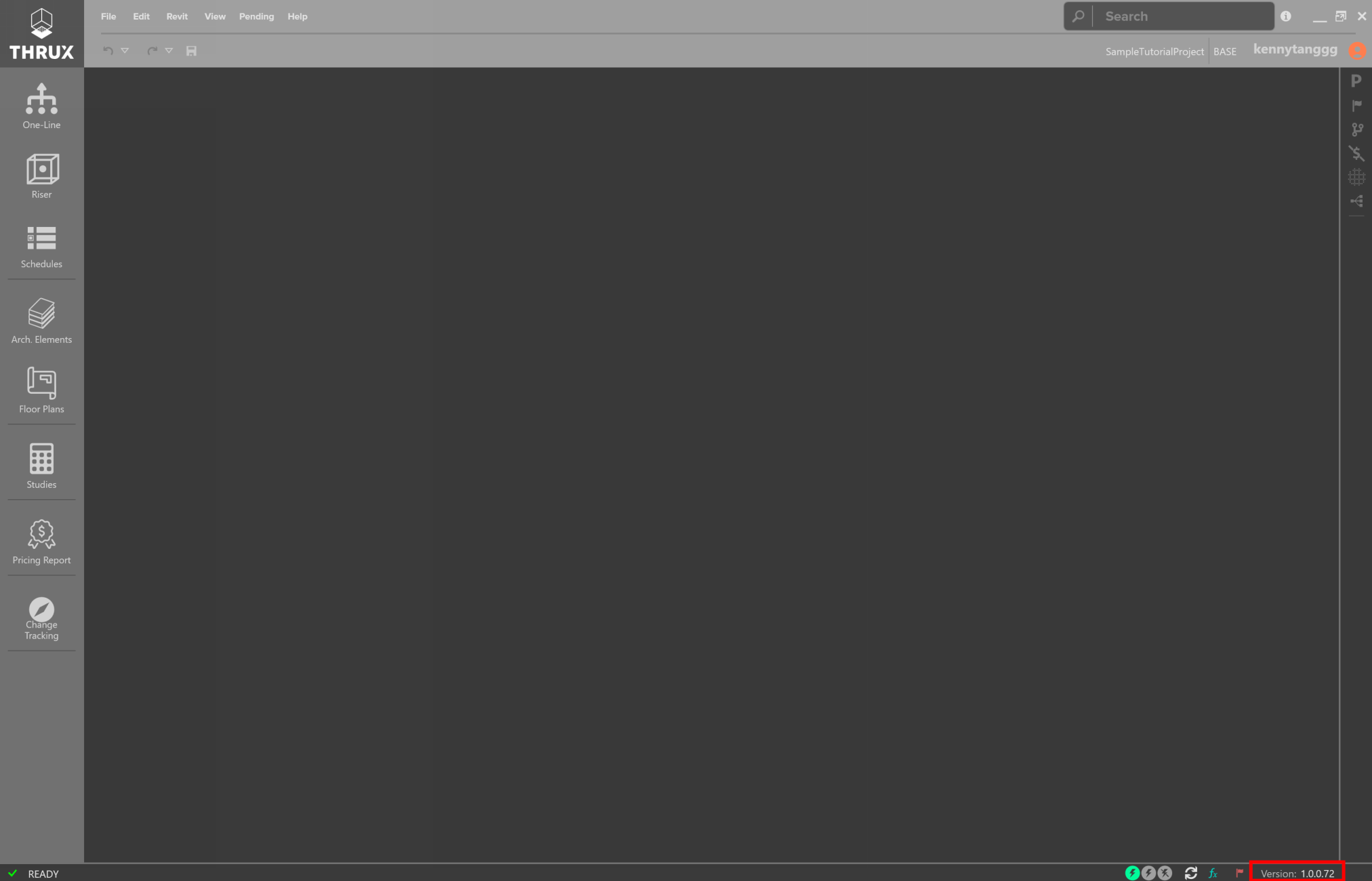
Whenever THRUX is opened, it automatically searches for updates.
Refer to the Version Number in the bottom right of the Status Bar.
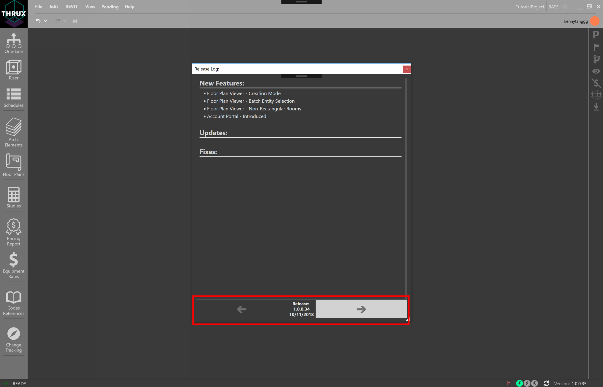
To see an outline of updates between each Version, click on the information icon located in the top-right of the top menu bar.
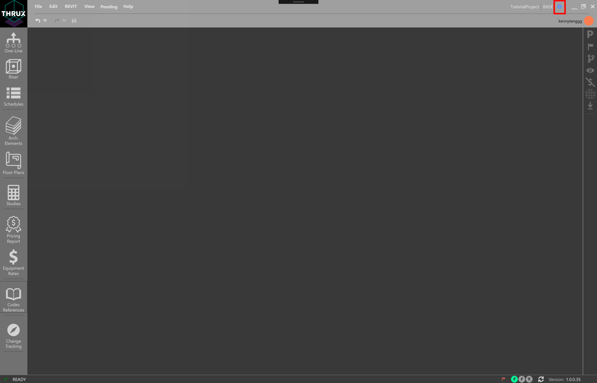
Use the arrows to navigate between each Version.
Revit Interoperability
The Architectural information which comprise the Architectural Workspaces, Arch. Elements and the Floor Plans, can be imported from a Revit model.
In addition, a THRUX model can be exported to Revit. You can then fine-tune Equipment locations using Revit, and verify the integrity of the design using THRUX.