General
Is THRUX compatible with Revit?
Yes, THRUX Pro provides the ability to Import/Export Revit models and THRUX models.
How do I export my drawings to AutoCAD?
Open the Schedules Workspace and open the Schedules you would like to export. Click the down arrow located in the top right, then click Export to AutoCAD.
See Exporting Schedules for more details.
I’m working in the One-Line. How do I create equipment?
All Equipment need to have a source of power, so make sure that a source such as a Utility or Generator exists first.
Use the Setup Wizard to create a source. Or, right-click inside the One-Line, click Add Source, then choose Utility or Generator.
If the source is not yet defined or known, create an Unhosted Equipment.
Right-click inside the Workspace, and then click Add Unhosted Equipment. Use the wizard to create the Equipment.
See Adding a Source or Adding Equipment for examples.
I’m not seeing everything on my Riser. I created equipment in the One-Line. How come it doesn’t show up?
Designers may perform loading calculations as part of the design process.
However, they may not want to show every piece of equipment on the Riser.
Use the Riser Toolbox to display the Hidden Elements.
I’ve created a Riser, but I’m starting to run out of space. Is there any way to shift everything upwards? If I move the floor will it update the elevations? Will it affect my lengths and voltage drop calculations?
The Riser Floor Elevations are not connected to the visual spacing between Floors.
Refer here for more information.
Is there a way to create groups of equipment?
Copying an Equipment will copy all of its downstream Equipment. Select the Equipment and use CTRL+C to copy.
Then select a new source and use CTRL+V to paste.
See here for an example in the One-Line or here for an example in the Schedules.
Is there a way to create a single feed for multiple motors or elevators?
By default, equipment is created on an individual circuit basis.
However, it is possible to create a single circuit which feeds multiple motors.
Create a Motor as a piece of equipment. Change the Quantity, and enter the load capacity for multiple motors.
A single OCPD and feeder will be sized based on the total load of the motors.
It is also possible to enter multiple motors with different load unit types.
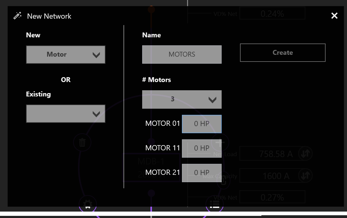
Using a single circuit to feed multiple motors
The same is true for elevators. If multiple elevator motors are selected, different diversity factors from the NEC are applied to the load.
I’ve created a network, but I forgot to add a distribution board, or transfer switch, or some type of intermediate node. How can I add this without deleting what I have?
It is possible to rehost circuits by dragging and dropping them from one source to another.
Simply rehost a section of the network to another source, then create the intermediate equipment, and reattach the network to the intermediate equipment.
See here for an example in the One-Line or here for an example in the Schedules.
How do I create a bus duct?
Select an Equipment, then select Add Equipment to create a Bus Duct.
See here for an example in the One-Line.
How do I connect a transfer switch?
After a transfer switch is created, connect its sources by selecting Add Equipment, and then click the Existing dropdown to select the transfer switch.
See here for more details. This is also available in the Schedules Workspace.
I’ve created my distribution network, but I haven’t assigned any Rooms yet. Is there a way to move my Equipment into Rooms?
In the Floor Plans, there is a Move Equipment function.
See here.
An alternative is to use the Riser. Place the Rooms on the Riser. Then drag the Equipment into their Room locations.
I have an existing building which I would like to model. Is it appropriate to use THRUX? How would I start? What’s the fastest way to do that?
Start with Design Assistance turned on.
Model each piece of equipment, then turn off Design Assistance and enter the information manually.
Also, make use of the Load Calculations to analyze different loading conditions.
I’ve turned Design Assistance off and manually changed feeder sizes. Is there a way to recalculate a circuit’s code-minimum requirements?
One option is to use Reset to Code Minimum. See here for an example in the One-Line and here for an example in the Schedules.
Another option is to turn Design Assistance on, and then change the Load Capacity.
How do I see what’s included in each update?
See Release Data.
Architectural
Do I need to create the Architectural Elements or do I need to use the Floor Plans Workspace?
No. These Workspaces aid in the design process and allow the designer to quickly alter the locations of Equipment in their design as the Architectural Elements change.
These Workspaces aid in calculating distances between Equipment, that affect point-to-point calculations.
Though it is highly recommended to use these Workspaces, it is also possible to manually enter all feeder and branch lengths.
I’m working in the Floor Plans. How do I create my columns and floors?
Use the Setup Wizard to create the XComp and YComp (column) components and Floors. Use the Grid Editor to modify the columns or manually modify these components in the Arch. Elements Workspace.
See Floor Plans or Arch. Elements for more information.
It is also possible to import this information from an architectural Revit model.
See here for more information.
Is there a way to move my equipment in one Room to another location?
Use the Floor Plans to shift Room locations. Move Equipment allows the ability to drag and drop Equipment into Rooms on the Floor Plans.
Or, manually modify the Room characteristics by using the Arch. Elements Workspace.
All Equipment in the Room will update their feeder lengths as the location changes.
I’m trying to enter decimal values into my floor heights. Why am I getting an error?
With floor heights, it is not always necessary to be very precise. Lengths of conduit runs can be modified using the Manual Added Length property. Voltage drop is also dependent on the size of the load, and the operating voltage.
Electrical Calculations
What is Load Capacity?
Load Capacity is a custom size modified by the designer.
With Design Assistance on, many properties of Equipment change as a result of changing the Load Capacity. For example, protective device sizes and conduit sizes are calculated based on the Load Capacity.
For example, if a designer entered 401A as the Load Capacity of a 3-ø Distribution Board, then a 600 AF, 450 AT breaker would be selected, fed via 3#600 kCMil phase conductors.
Is there a way to manually override a load?
Net Load is a calculated value which is determined by the sum of the loads.
It can be overridden to manually override the calculated value.
Setting the Net Load will ignore all downstream loads, and set the load of the Equipment to be the specified value.
This can be helpful when designing around theoretical load conditions.
The overridden value will take precedence over normal calculated loads which are based on what the connected load.
Designers also have the option to diversify loads and apply custom diversity factors. Load Overridden values take precedence over normal loading calculations.
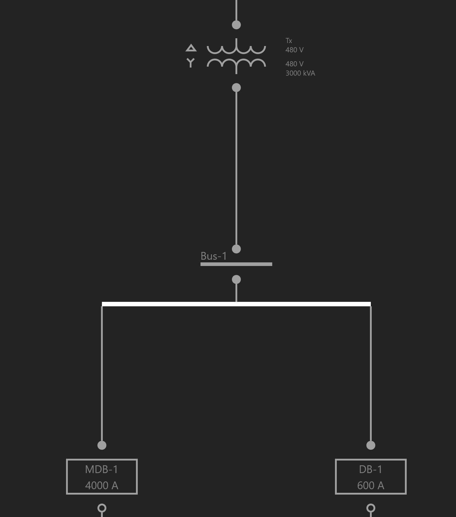
In the example below, a Distribution Board feeds two Distribution Boards, each with two Generic Loads. All Equipment do not have any % Design Spare Capacity. Setting the Load Override of an Equipment to be a value causes the Net Load to read that value. If the Load Override is null, the Net Load consists of the normally calculated value based on the Connected Load. Consequently, the Net Load of the upstream distribution board consists of the sum of its children’s Net Loads.
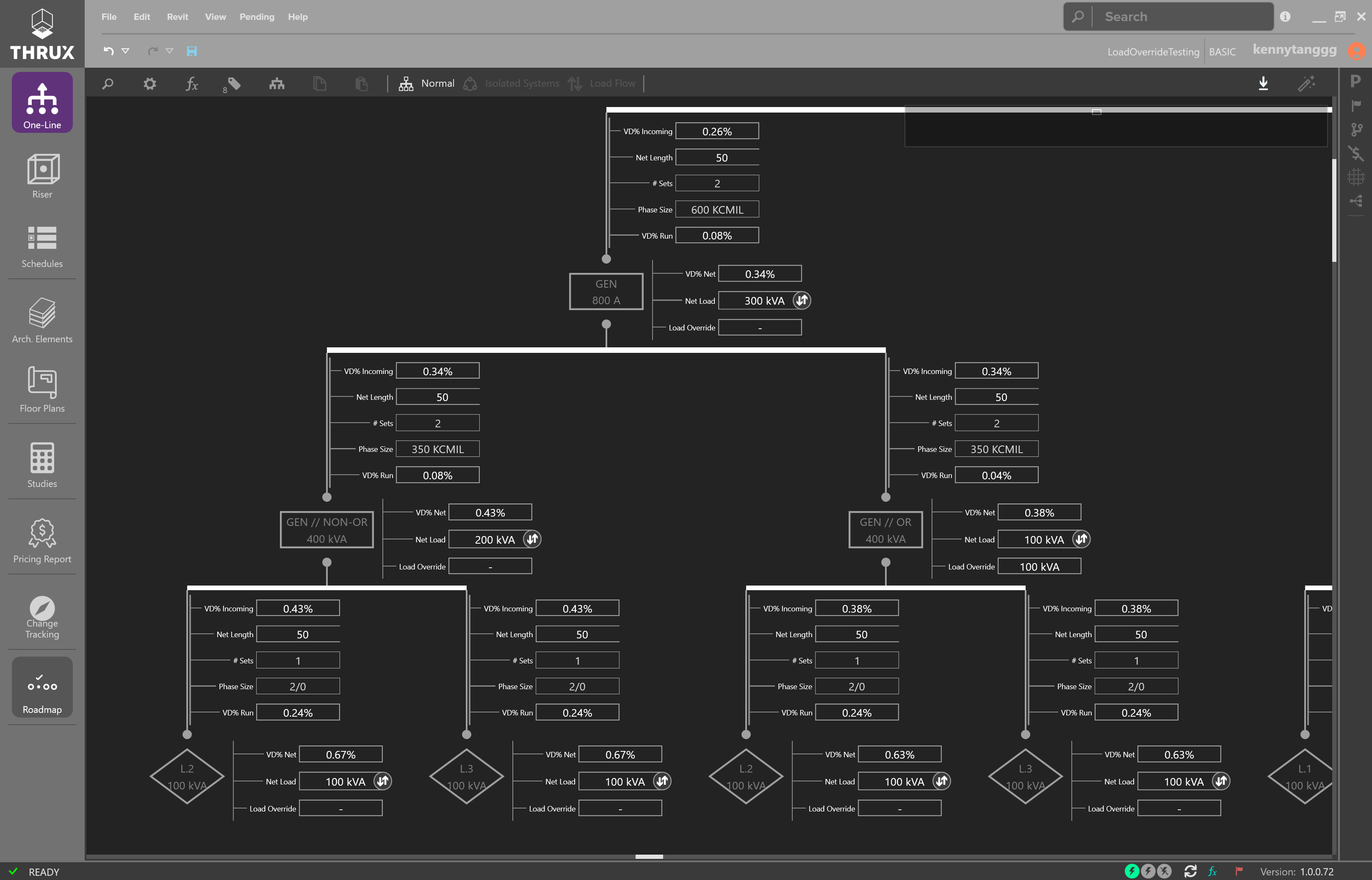
Load Override
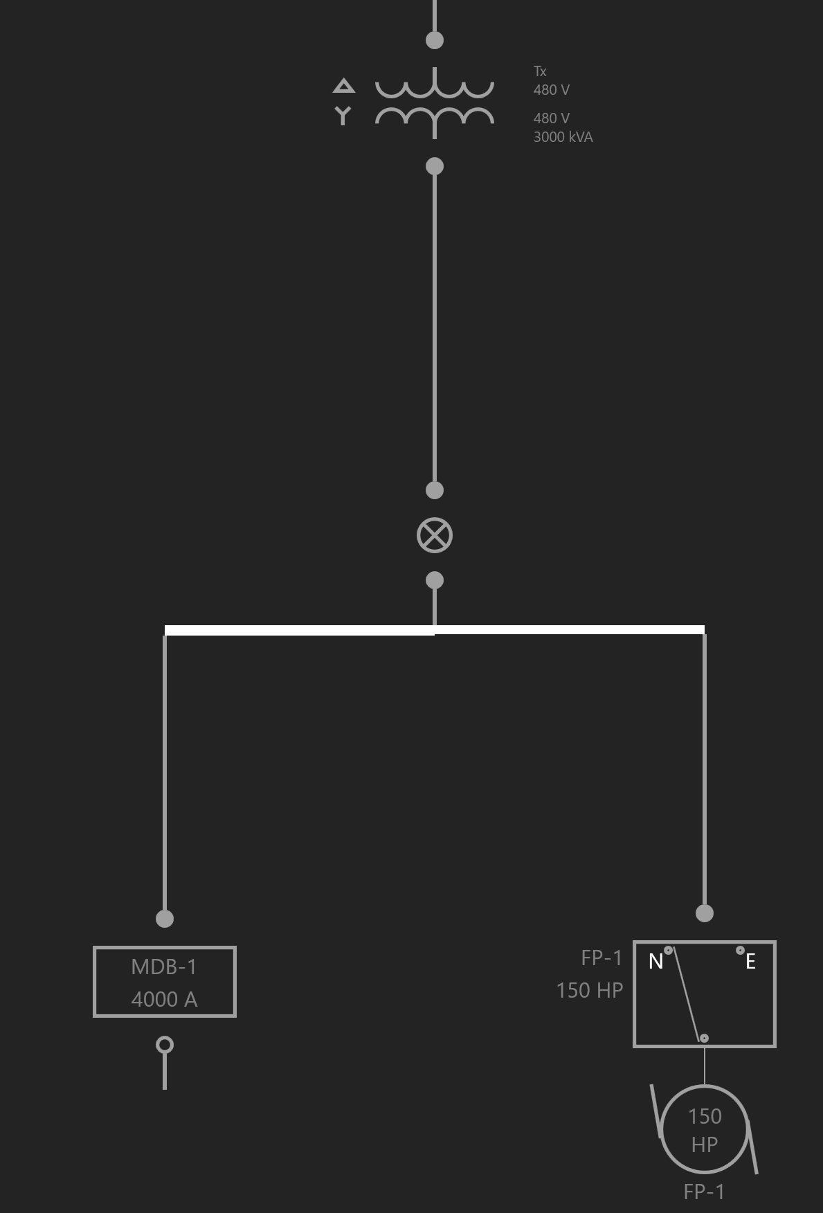
Load Override allows a designer to forecast the effects of a load on a system. Use the Load Flow View to further analyze the system.
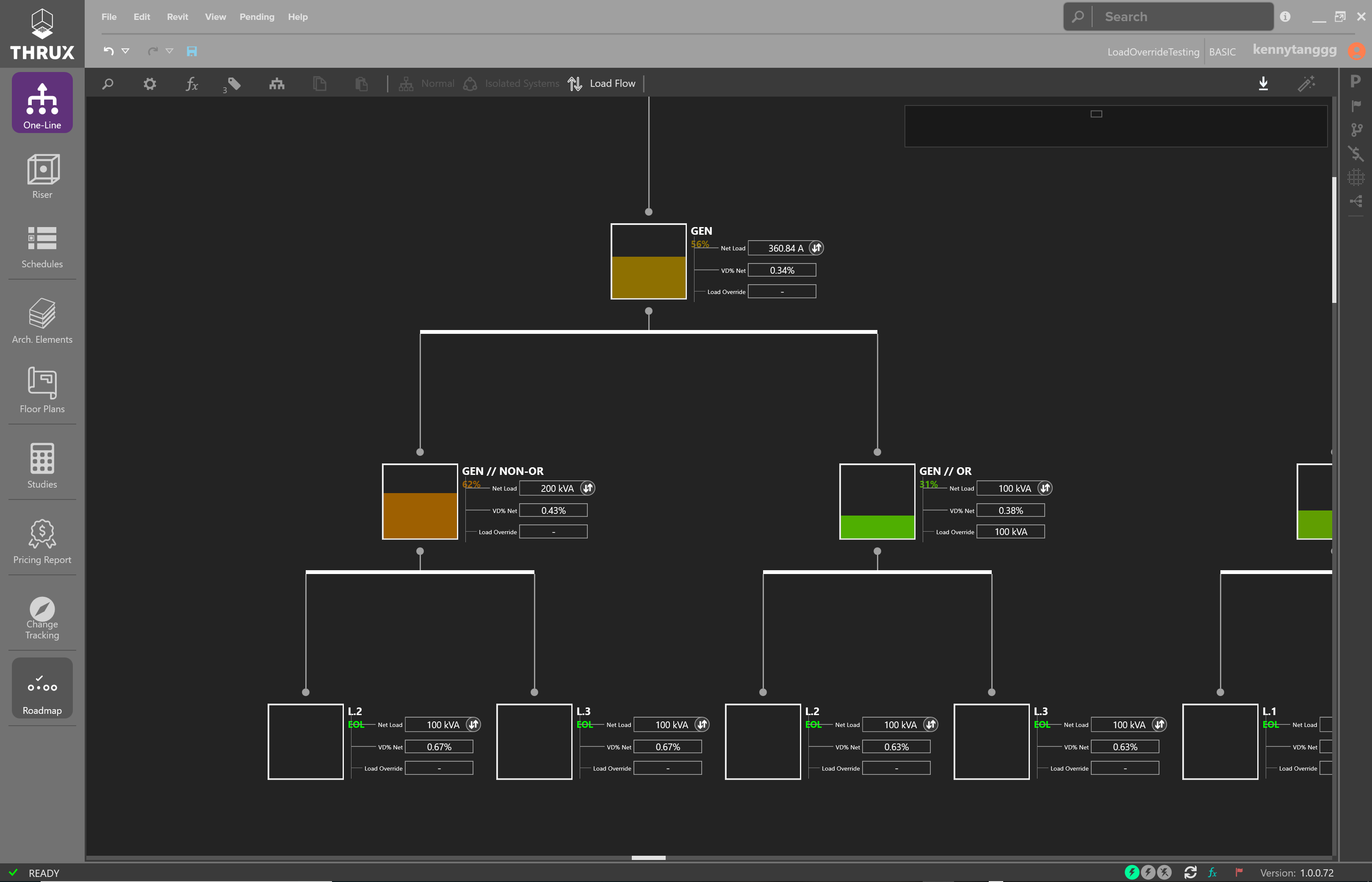
Viewing the One-Line in Load Flow View
What is % Design Spare Capacity?
% Design Spare Capacity is an adjustment factor that is based on the Code Demand Load.
For example, if a Distribution Board has a Connected Load of 20 kVA and also has a % Design Spare Capacity of 50%, the Net Load on the Distribution Board, DB-1, will be 30 kVA. This is due to the 20 kVA Connected Load, in addition to the 10 kVA of Design Spare Capacity.
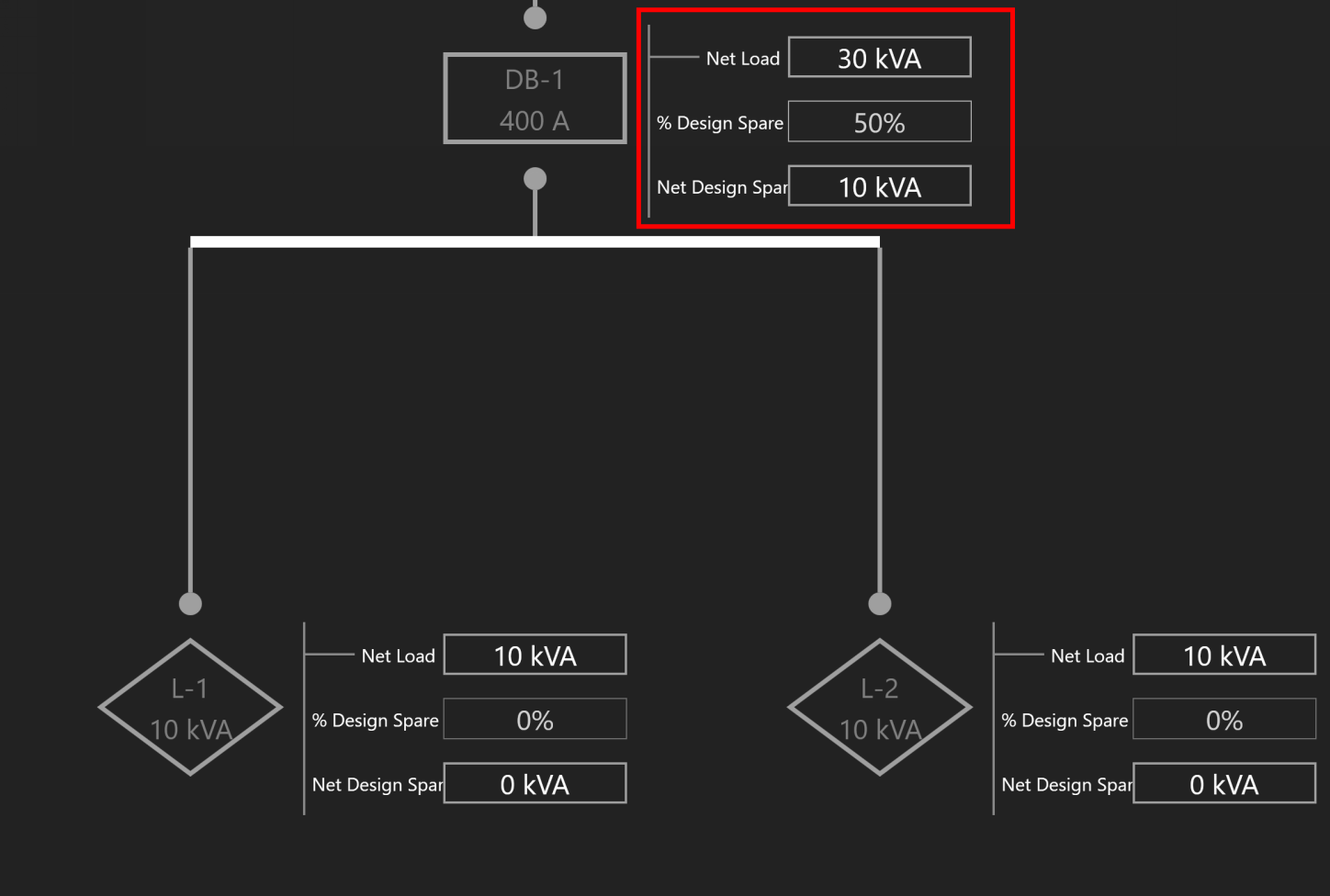
Design Spare Capacity
What is Net Load?
Net Load consists of the connected load. The connected load can be driven by equipment loads, residential loads, diversified loads, design spare capacity, and overridden loads.
How do I enter the available SCC from the Utility?
Select the Utility source. Under the Miscellaneous property grouping, enter the value under Available SCC (kA).
See here for an example.
How is the Length of a Bus Duct Determined?
A Bus Duct must be assigned to a Room. All branch loads of the Bus Duct must also be assigned to a Room.
Pipe and wire is used until it terminates and transitions to a Bus Duct at the Room of the Bus Duct. In other words, the length of the pipe and wire run is the distance between the Room of the source distribution equipment and the Room of the Bus Duct.
The vertical run of the Bus Duct is determined by the vertical distance between the Room of the branch load and Room of the Bus Duct.
Pipe and wire is used for branch circuits of the Bus Duct. The length of the run is determined from the distance between the Room of the Bus Duct, and the Room of the load.
How do bus duct voltage drop calculations work?
Bus Duct voltage drop calculations are split into different sections.
The first section is the voltage drop calculated across the pipe and wire portion. This length is dictated by the distance between the source Equipment Room location, and Bus Duct Room location. The load is based on the Connected Load of the Bus Duct.
The second section is the voltage drop calculated across the vertical run of the Bus Duct. The impedance of the Bus Duct is determined by its vertical run. The vertical run is determined by the Bus Duct’s Room location, and the branch circuit load’s Room location. The voltage drop across the vertical run is based on the Connected Load of the Bus Duct. As multiple circuits are added to the Bus Duct, the load tapers throughout the length of the Bus Duct, and voltage drop calculations are recalculated.
The final section is the voltage drop calculated across the horizontal run to the branch circuit load. The horizontal length of the run is determined by the Room of the Bus Duct and the Room of branch circuit load. The load is determined by the branch circuit load.
I know the area or square footage of a space. How do I model that as a load?
Floors and Rooms are Architectural Elements which can be used to perform load calculations.
Both of them have an Area and a SpaceType which allows you to calculate a load density.
This load density can be placed or attached to different points in your system.
The Area can be calculated or manually entered as a custom value.
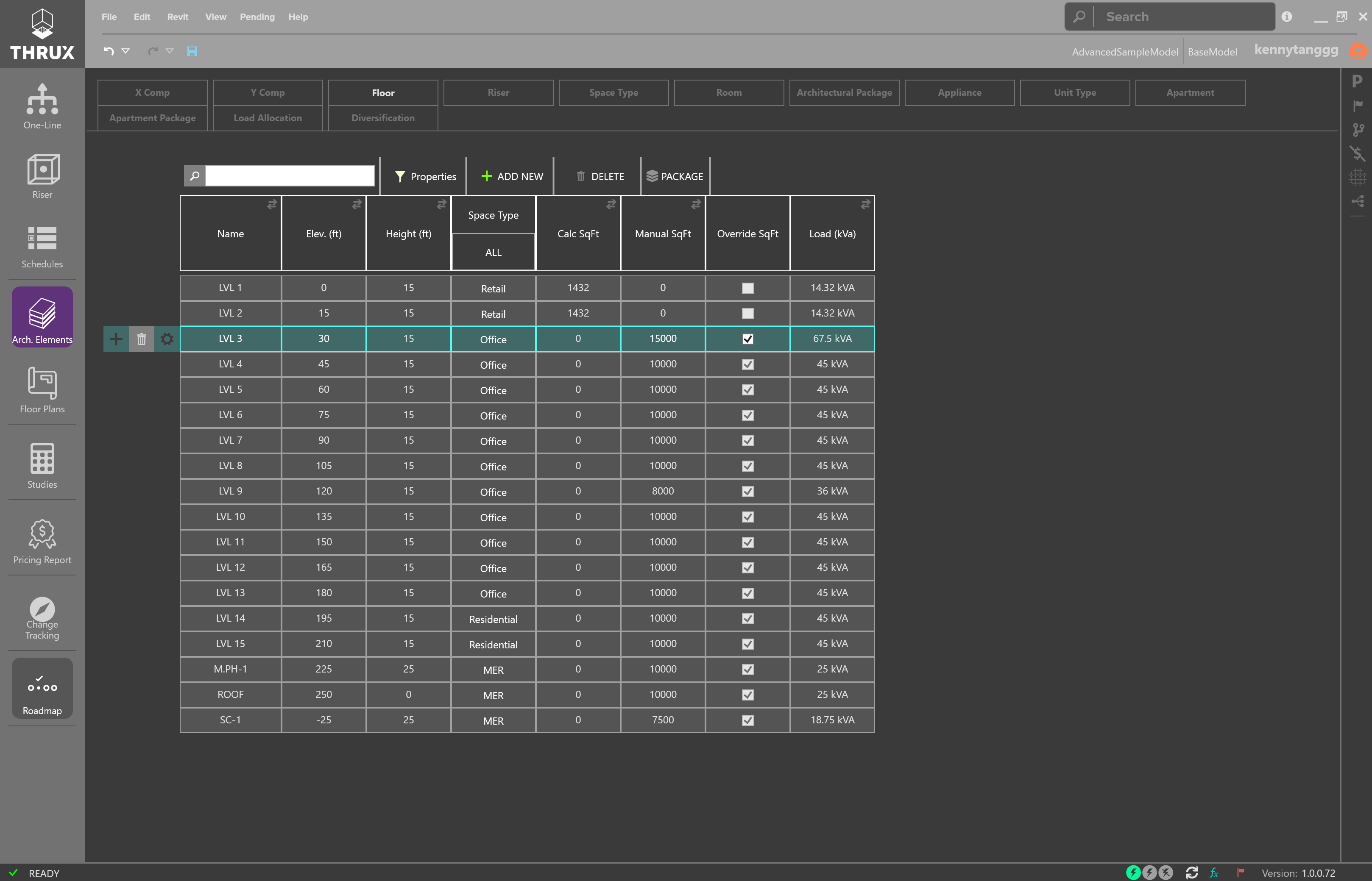
The Floor tab of the Arch. Elements
How do residential load calculations work?
Residential load calculations are based on the variety of Appliances which require power in a Unit Type. Apartments are each assigned a Unit Type. Apartments can be grouped together into Apartment Packages. Depending on the number of dwelling units, different diversity factors are applied to the load.
Appliances can be categorized into different classes such as Small Appliance, Fixed Appliance, Range, Dryer, Heating / Air Conditioning, as defined by the NEC.
Unit Types can hold a variety of Appliances. Apartments are each assigned a Unit Type. There are two types of load calculations performed on an Apartment: Standard and Optional. Each calculation takes the sum of the load of each Unit Type’s Appliances and applies different diversity factors.
For Apartment Packages, the same two types of load calculations apply, based on the collections of Appliances. However, there is a third calculation, known as a multi-dwelling calculation, which is used if there are more than two Apartments. The multi-dwelling calculation applies a demand factor based on the number of Apartments.
The overall load of the Apartment Package is determined by the minimum of the three (3) load calculations.
How do I model a tap?
To model a tap, create a Tap Node or Bus Node in between the source and the load.
How do I Diversify Loads?
It is possible to apply custom diversities to different sections of the distribution network.
See Diversification.
Is there a way to implement a conditional constraint for sizing Equipment of loads greater than a specific amperage to require copper over aluminum?
Coming soon.