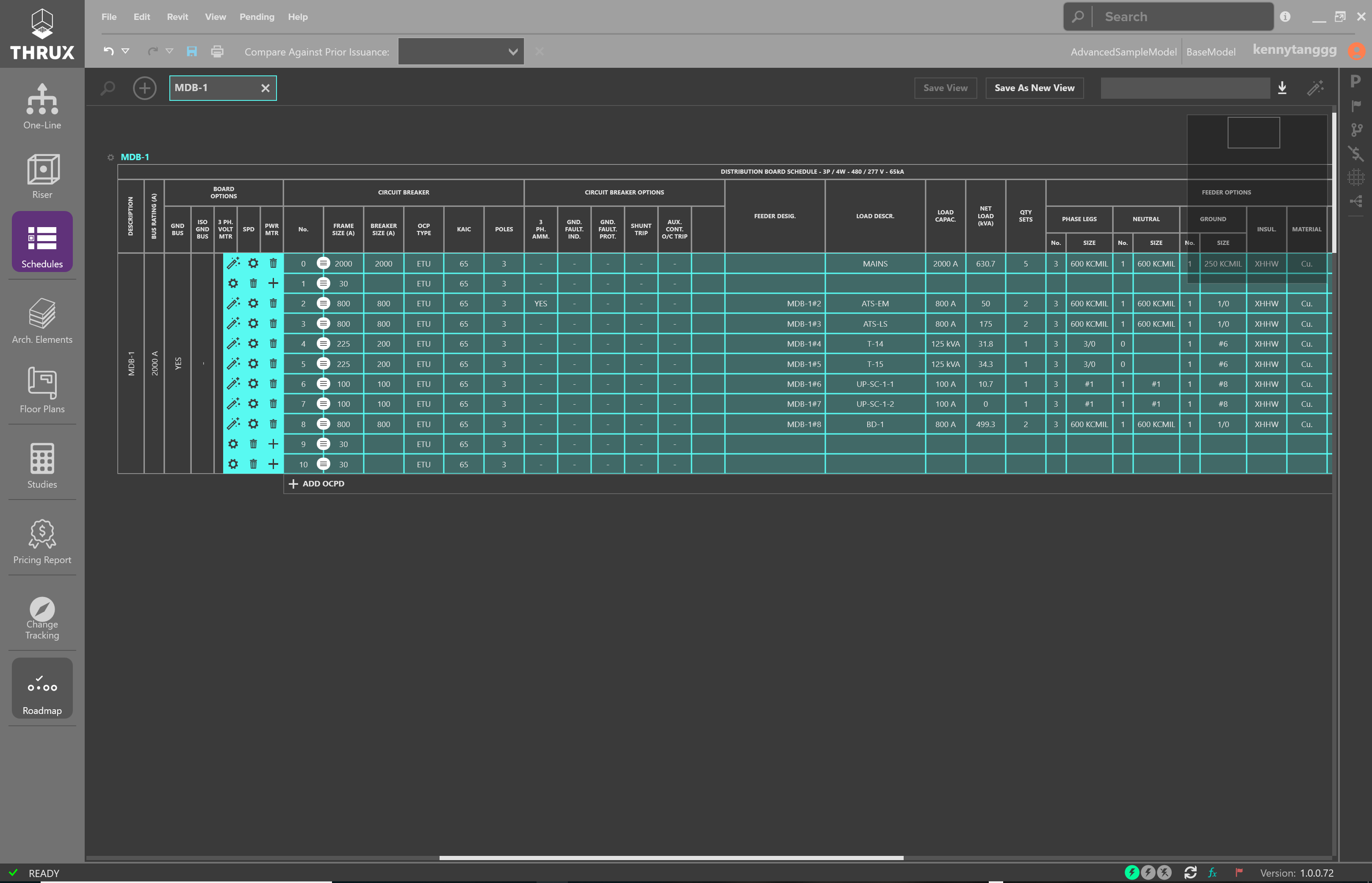
Schedules are a tabular representation of the distribution system. This is a great environment to rapidly create distribution systems. Schedules are primarily used for Distribution Boards, Switchboards, and Panelboards. Not every piece of Equipment has a dedicated Schedule.
The top portion of the Workspace shows all open Schedules. A selected item will highlight on the corresponding Schedule. Schedules can be exported to AutoCAD or Excel.
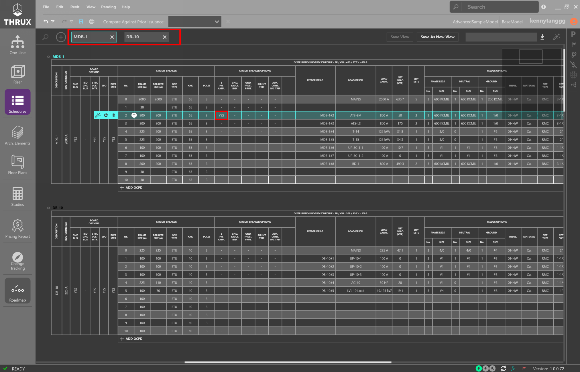
Open Schedules and selecting circuit breaker options
Open Schedule
To open an existing Schedule use the Add (+) button.
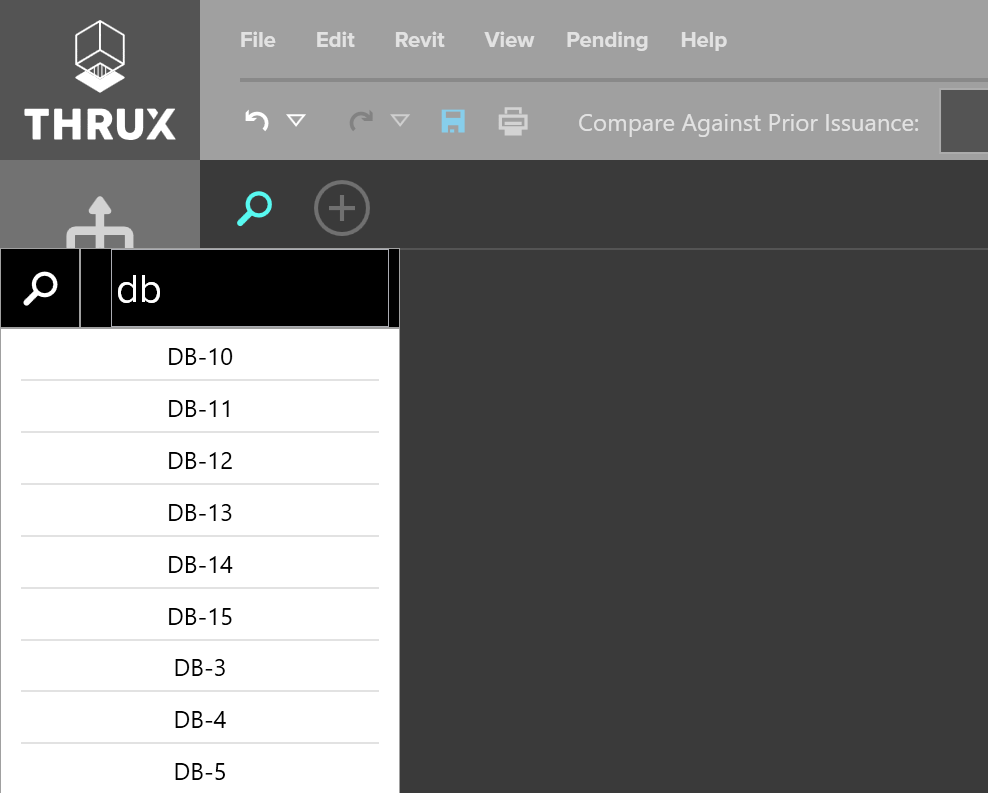
Using the Add button to open Schedules
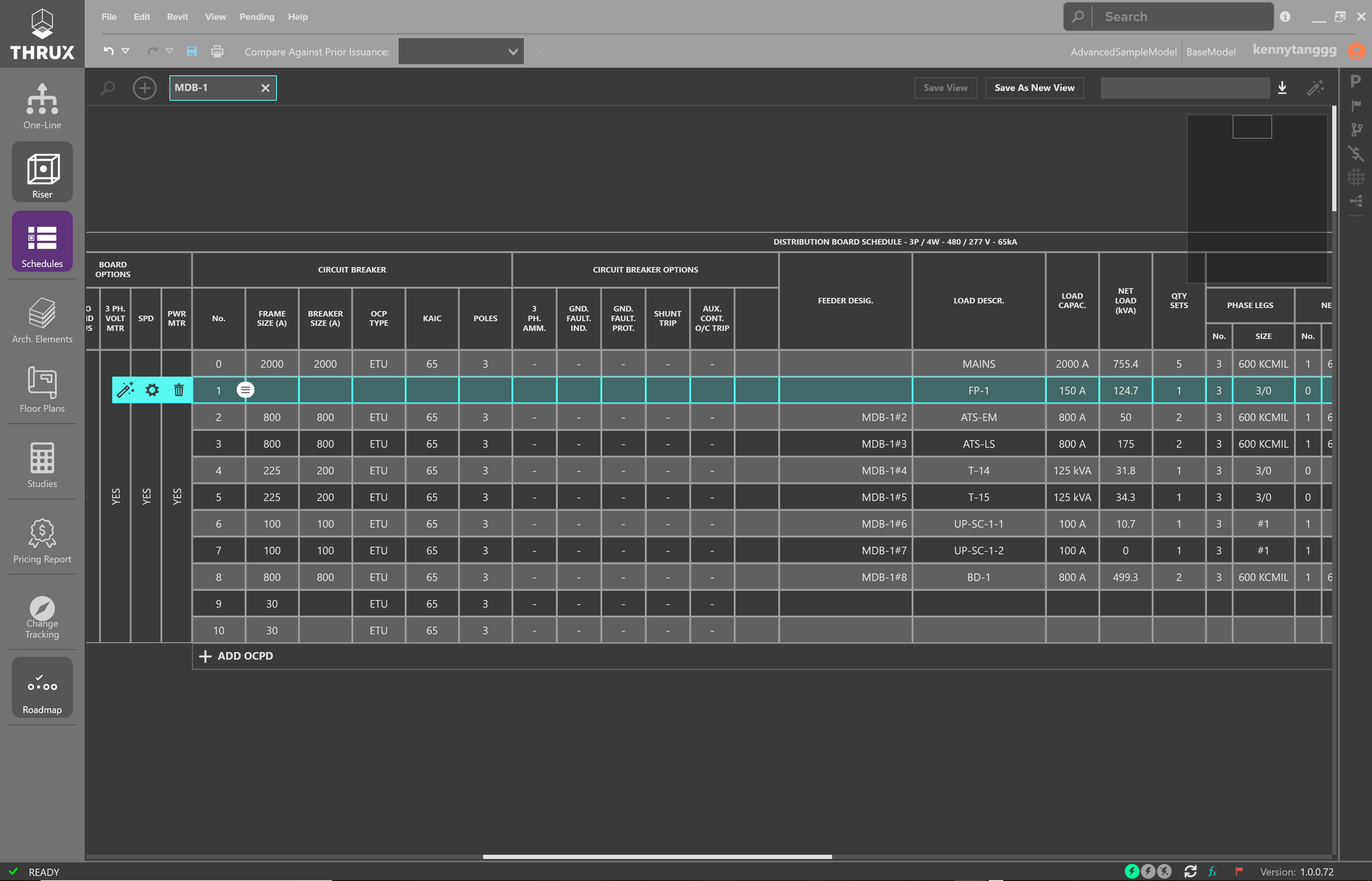
Adding, Deleting, Editing Equipment
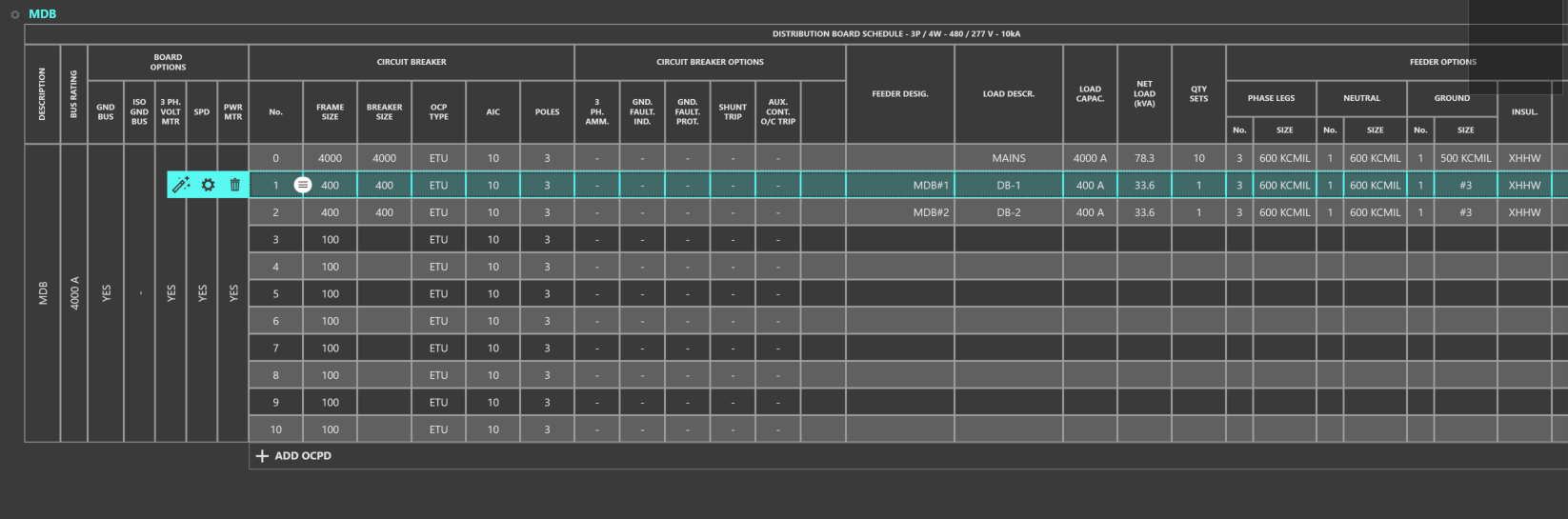
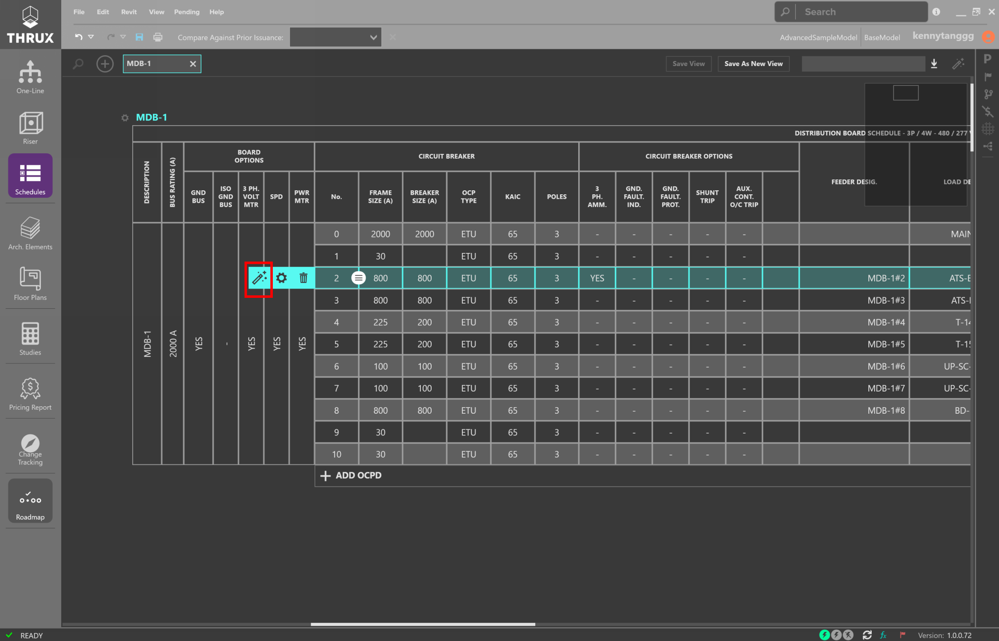
Clicking on a circuit number selects a circuit. With an empty circuit selected, note the options to Add Equipment (+ icon), or Delete (trash icon), or Edit Properties (gear icon).
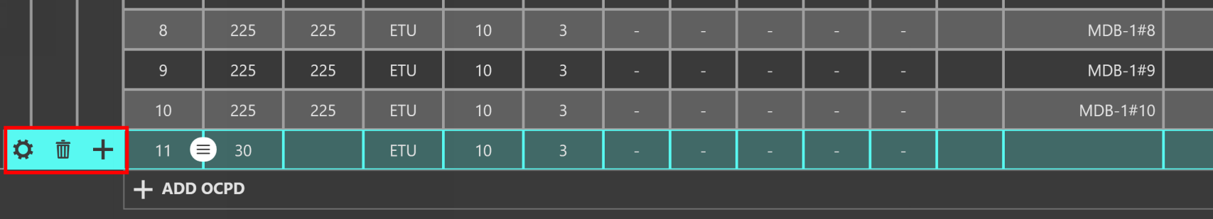
Editing a space on a Schedule
Deleting a circuit that has a connected load will prompt you to delete the selected Equipment or the entire downstream network. The OCPD will reset to the smallest available size.
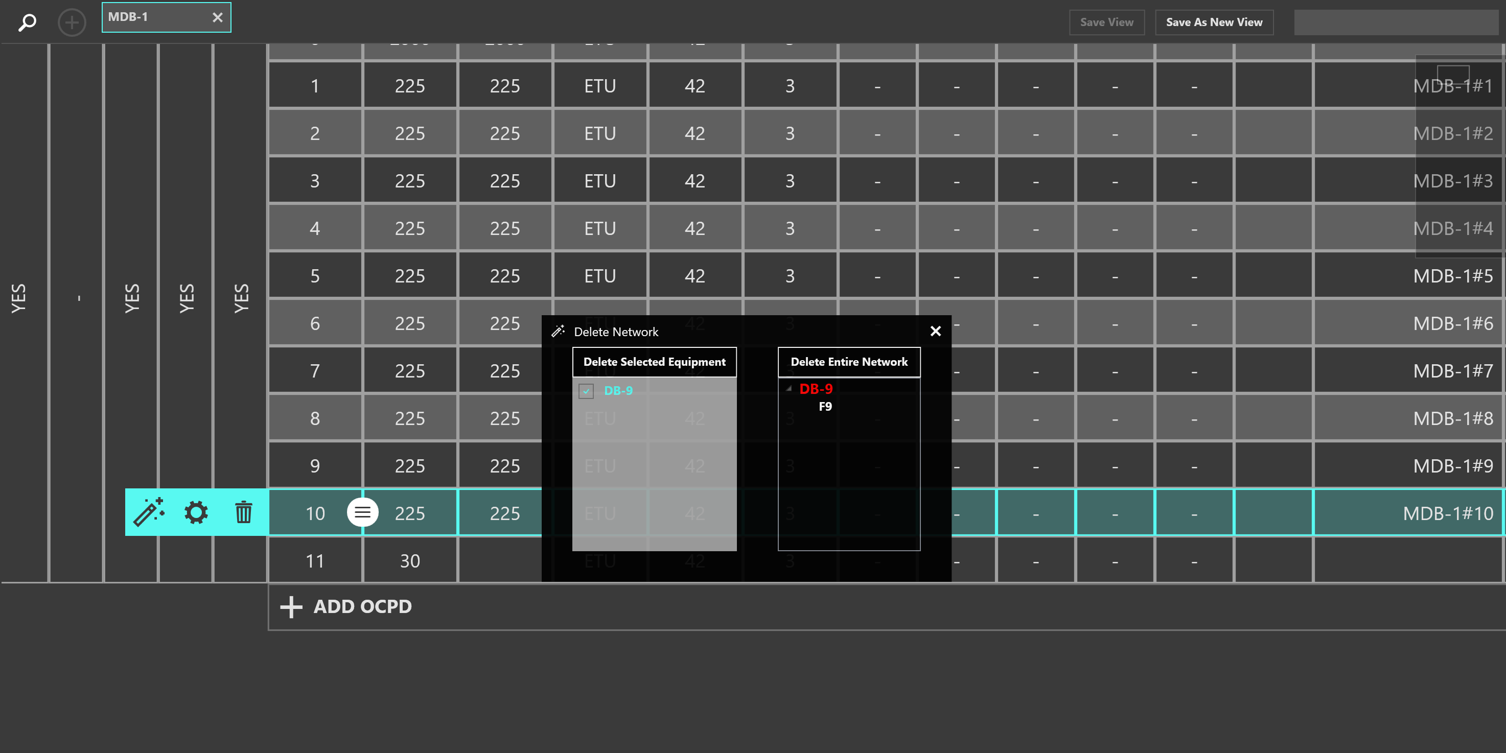
Deleting the selected Equipment or its entire downstream network
Deleting a circuit with a connected load resets the OCPD to the smallest possible value
Deleting an empty circuit or a circuit without a connected load deletes the OCPD
Copy/Paste Circuits
Copying, Deleting, and Moving Equipment in the Schedules Workspace is similar to the interactions in the One-Line.
Once a Schedule is open, to copy a circuit select the circuit number or click the circuit breaker number. Selection will be highlighted.
Selecting a circuit
Next use CTRL+C to copy or CTRL+X to cut. The selection will highlight to a different color and be added to the clipboard.
Copying or cutting a circuit
Then, select the source or Equipment to paste to and click Paste or use CTRL+V. Equipment can be pasted on the same Schedule, or other open Schedule.
Select All
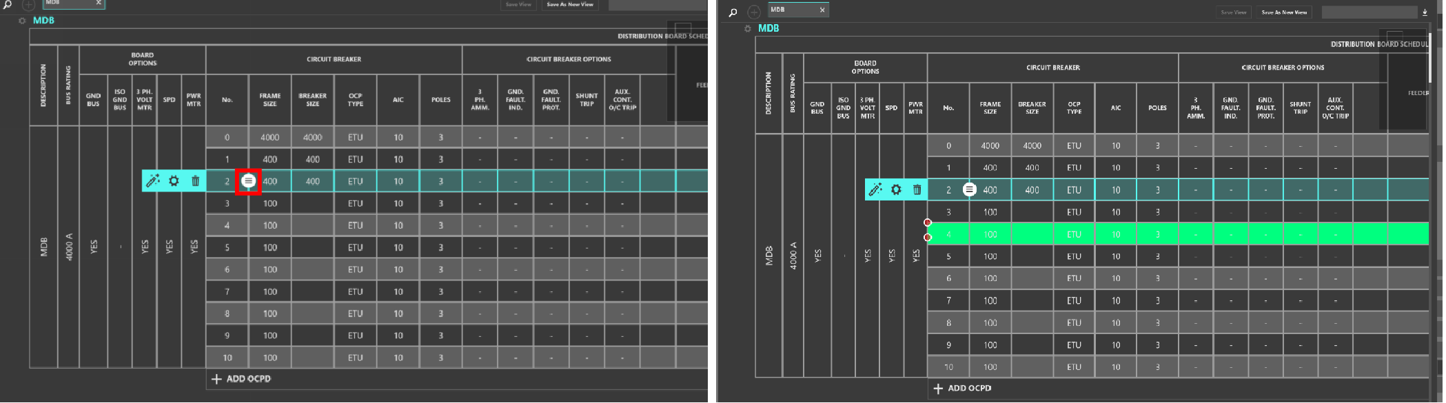
To select all circuits of a Schedule, first select the circuit number or click the circuit breaker number.
Then use CTRL+A to Select All circuits.
All circuits selected are highlighted
Reset to Code Minimum
THRUX can automate the selection of many parametric components, but these can also be manually modified. You can reset the circuit properties to be the code-minimum value, based on the Load Capacity.
Select the circuit number, then click Reset to Code Minimum (wand symbol). Or, right-click the circuit, and then select Reset to Code Minimum.
With Design Assistance enabled, THRUX will automatically calculate code minimum values, such as OCPD size, conductor size, and conduit size, when the Equipment’s Load Capacity is changed.
Select a circuit and use the wand symbol to reset the circuit its code-minimum values
Moving, Rehosting Equipment, or Reordering Circuits
The ordering of circuits can affect the overall construction of the board. To move circuits, select the circuit number and then click and drag the Grip (grip icon).
Selected circuit is highlighted. Use the grip to move the circuit to a separate space
Another way to rehost circuits is to right-click on a circuit, and select Move/Rehost.
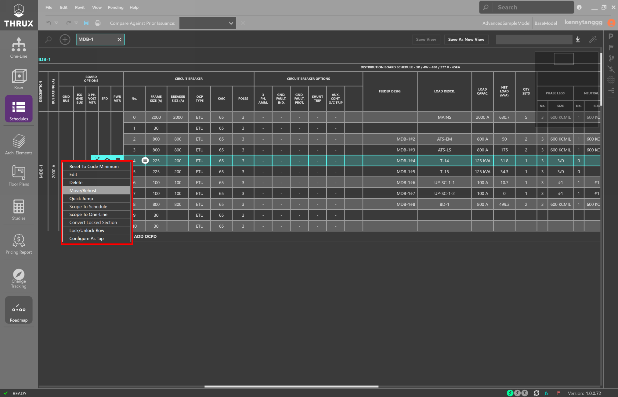
Right-click on a circuit to rehost it
Lock/Unlock
You can lock a selection which will prevent elements from being modified. Select a circuit number and then click the Lock/Unlock (lock symbol) button.
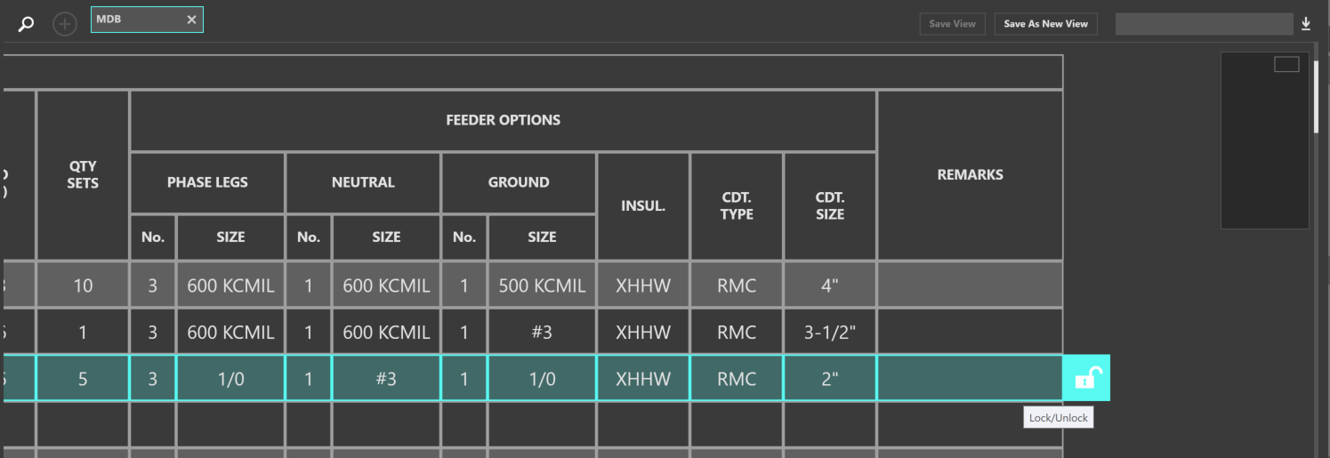
Unlocked circuits are free to be modified
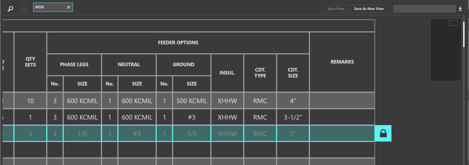
Locked circuits are shaded
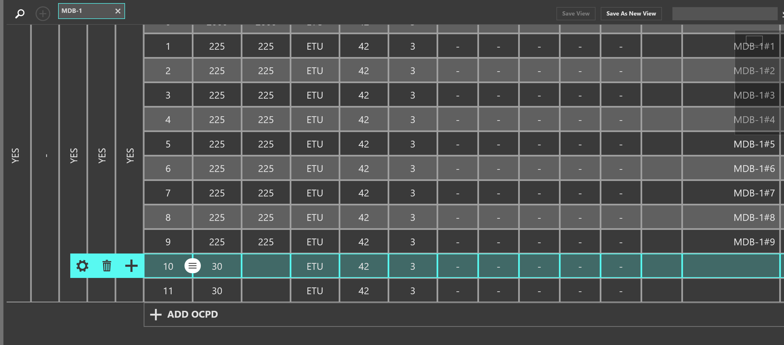
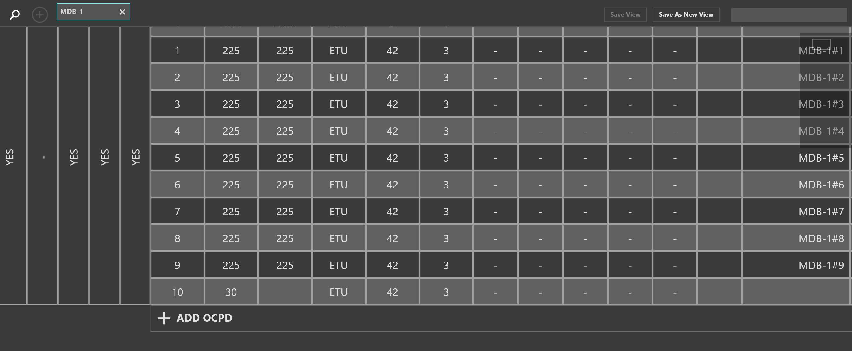
Adding OCPD’s
The amount of protective devices a distribution board supports is proportional to its physical installation. Equipment cannot be added to a distribution board unless there is space alotted.
To add a protective device, click Add OCPD.
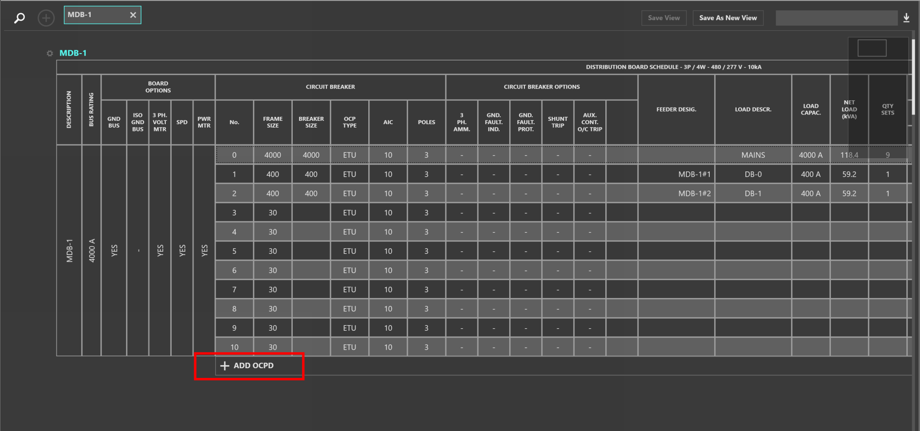
Adding an OCPD to a Schedule
Navigate
Right-click on a circuit element to open a utility menu. You can navigate to other Schedules or to the One-Line by selecting Scope to Schedule or Scope to One-Line.
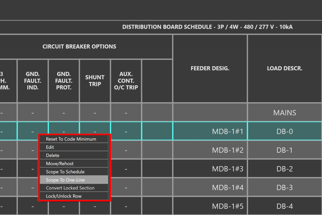
Navigating to the One-Line from a Schedule
Comparing Schedules Between Branches
It is common to identify changes between Issuances or Branches.
Use Compare Against Prior Issuance to compare Issuances. In the example below, we’re comparing a Schedule of a main distribution board used in two Issuances.
In the BASE Issuance we’ve used copper conductors, while the other Issuance is using aluminum conductors.
Open a Branch and open the Schedules you would like to compare.
This feature allows the designer to track changes between Issuances.
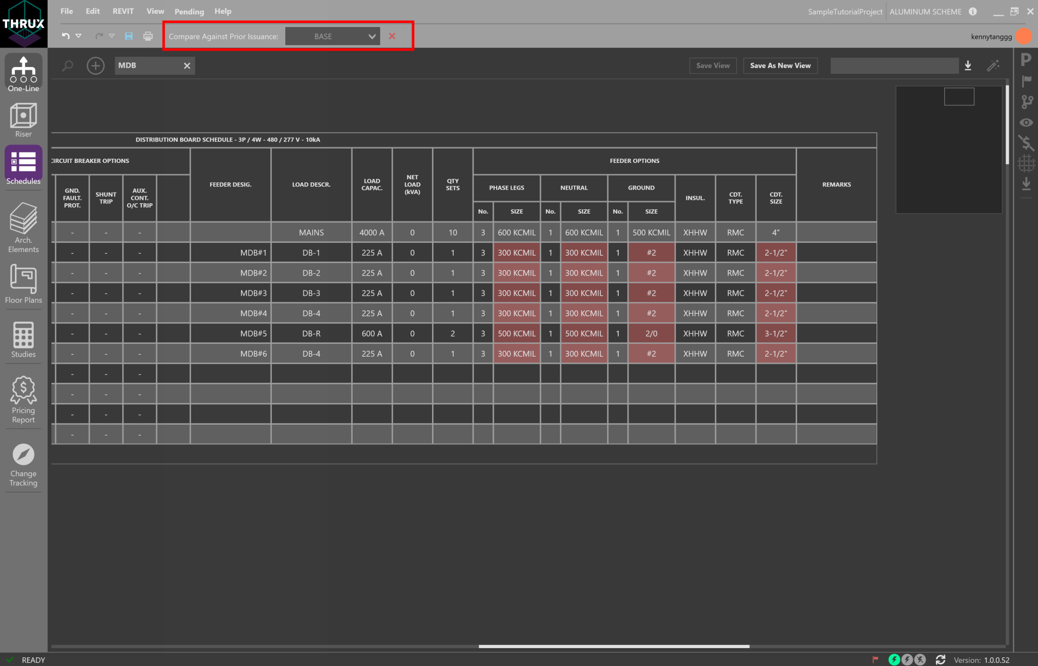
Changes Between Issuances
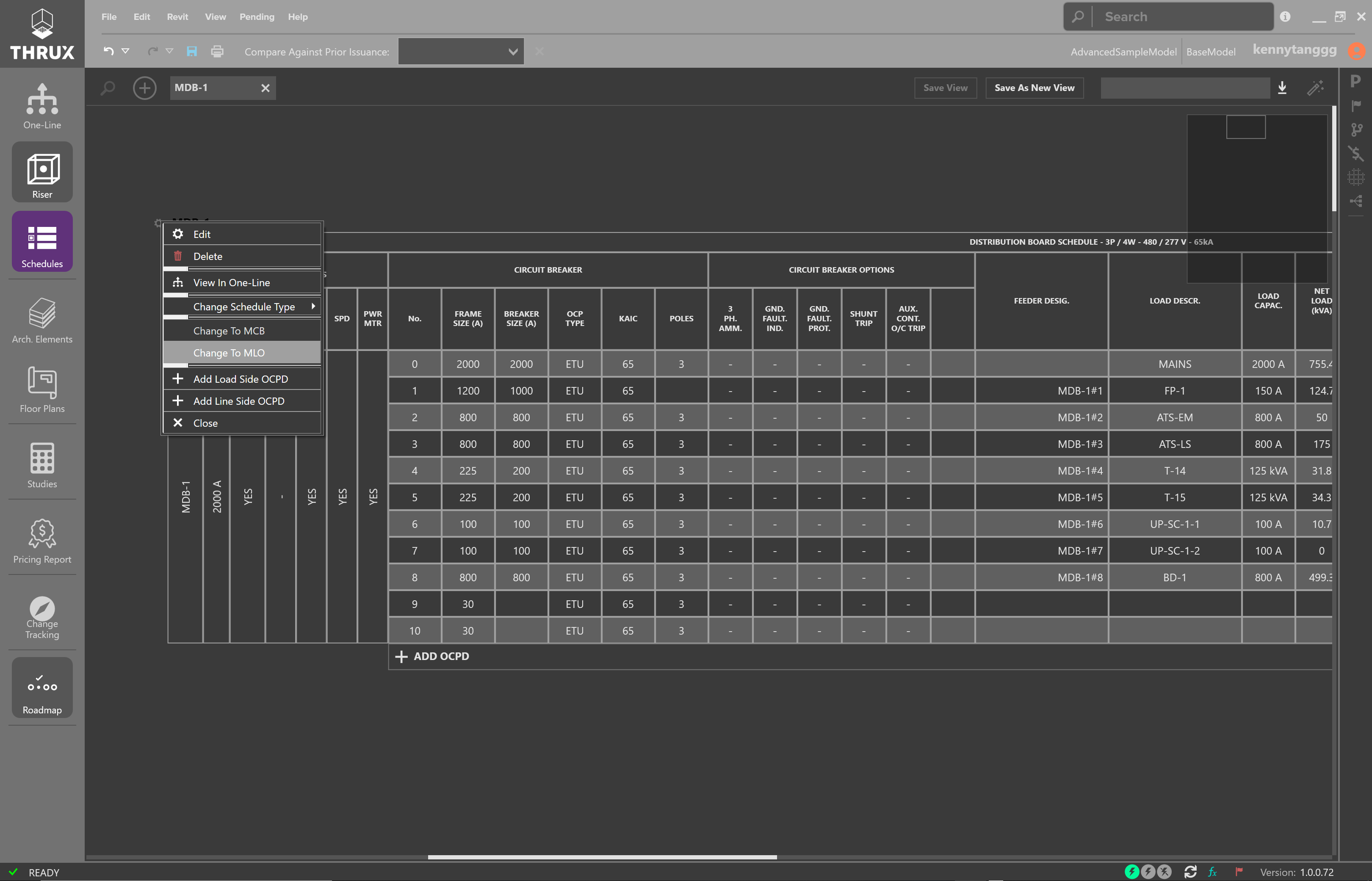
MLO - Main Lug Only
Distribution equipment can be equipped to have a main protective device or without, otherwise known as MLO (Main Lug Only).
To configure your distribution equipment as MLO, click on the settings icon (gear). Then choose Change to MLO.
Change to MLO
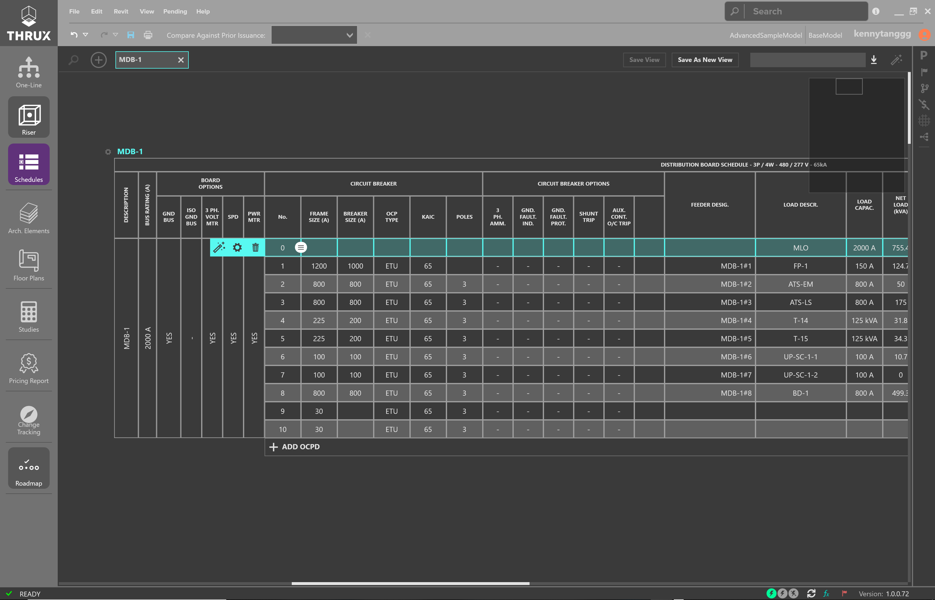
Changing the Load Description to denote MLO
Configure as Tap
A common type of electrical connection is a tap. Taps can be within the electrical equipment, or external.
If they are internal, right-click on a circuit and use Configure as Tap. If they are external, create a Tap Node.
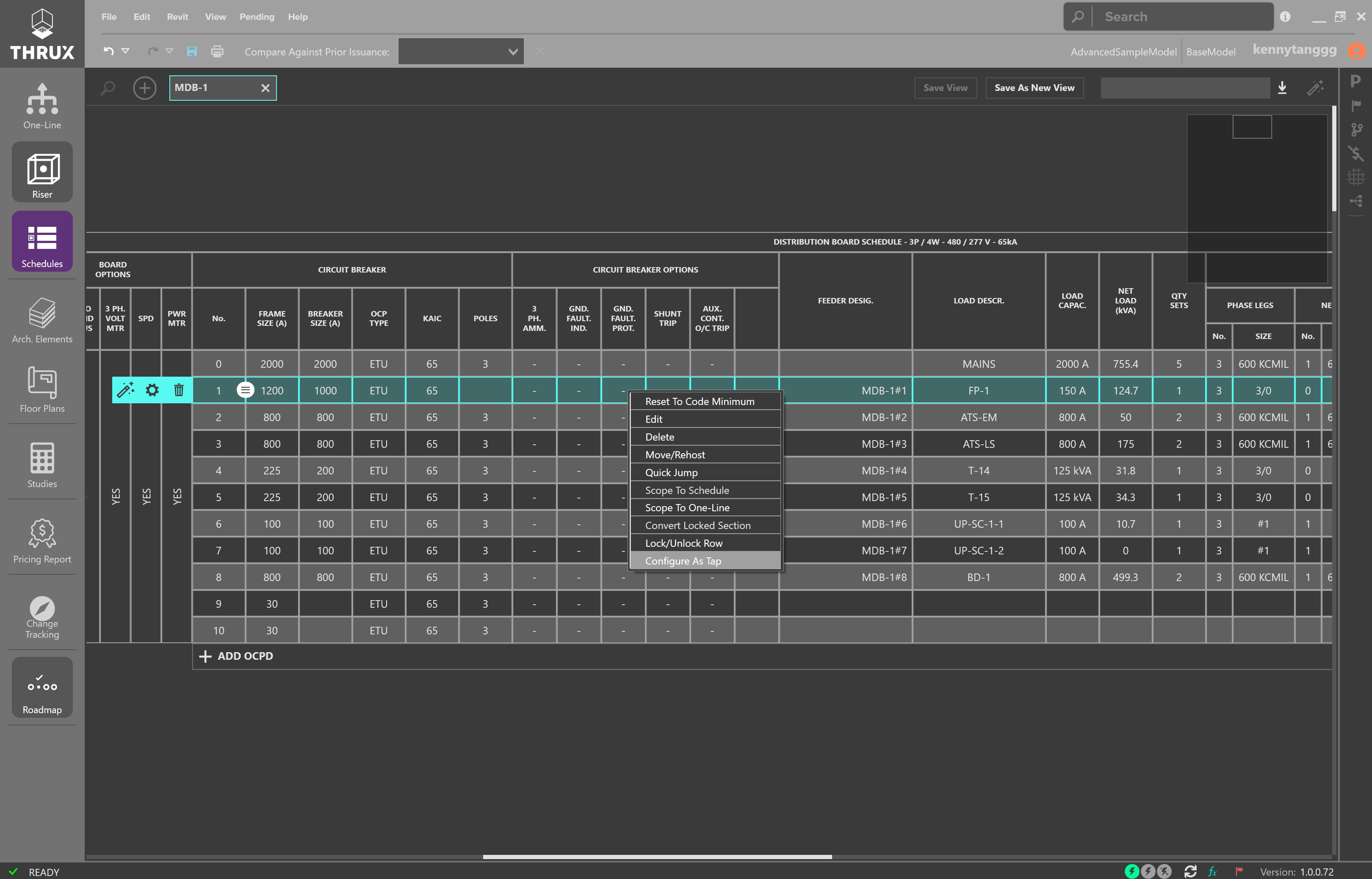
Right-click a circuit and use Configure as Tap
Internal taps remove OCPDs on the line side of distribution equipment.
Right-click a circuit and use Configure as Tap
Converting Breaker/Switch and Fuse
By default, Distribution Boards use breakers as protective devices, while Switchboards use switch and fuse as protective devices. To convert a board’s protective devices, click the Settings (gear symbol) button in the top left of the Schedule. Then, under Change Schedule Type, select Convert to Switch/Fuse.
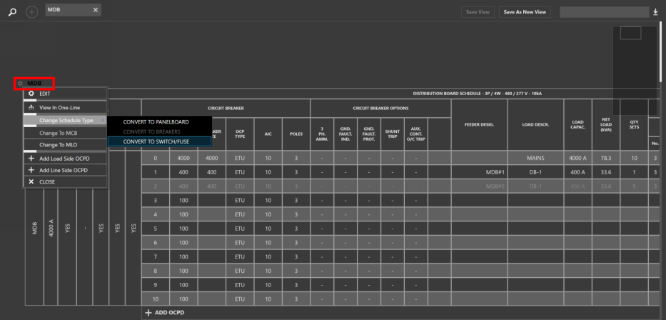
Converting a Distribution Board to a Switchboard will change its protective devices from circuit breakers to switch and fuses
Multi-Pole Circuits
Panelboard Schedules have the ability to convert single pole circuits to multi-pole circuits.
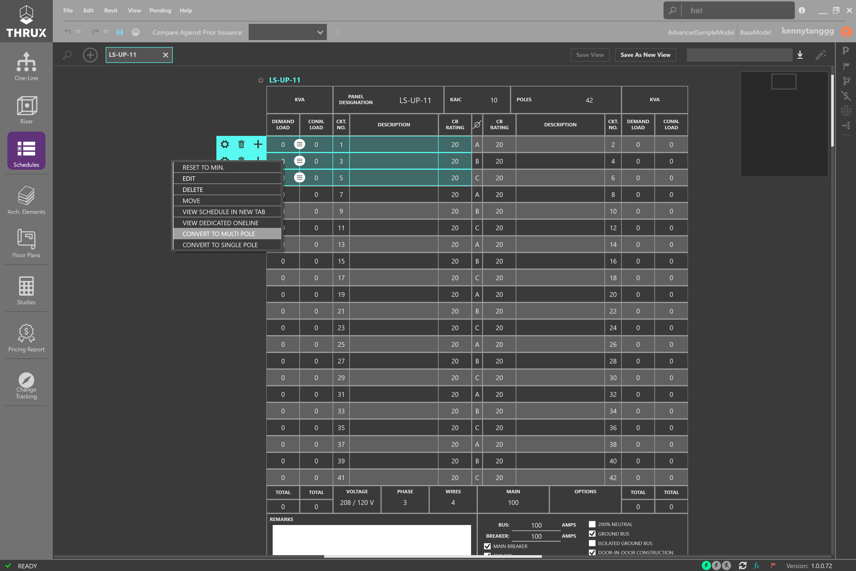
Select multiple circuits, then right-click, and choose Convert to Multi-Pole
Poles
Panelboard Schedules are commonly installed in configurations of 18, 24, 30, 36, and 42 Poles.
By default, Panelboards are installed with 42 Poles.
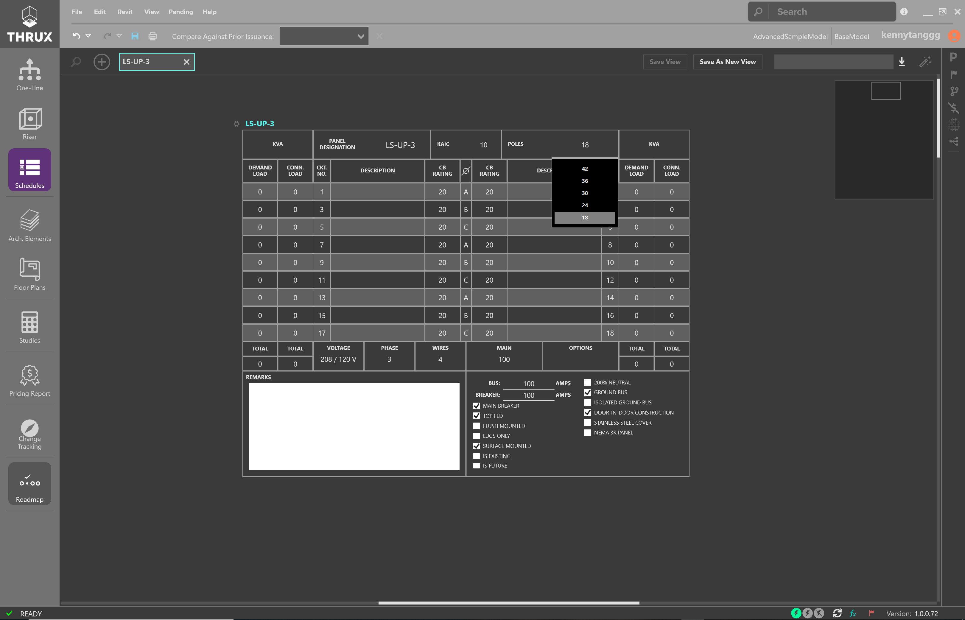
Changing the number of Poles
Schedule Views
Groups of Schedules can be saved for a later viewing. Open all of the Schedules to be grouped, then click Save As New View, and enter a name. Return to this view at any time.
In this example, two Schedule Views have been created, and you can toggle between them.
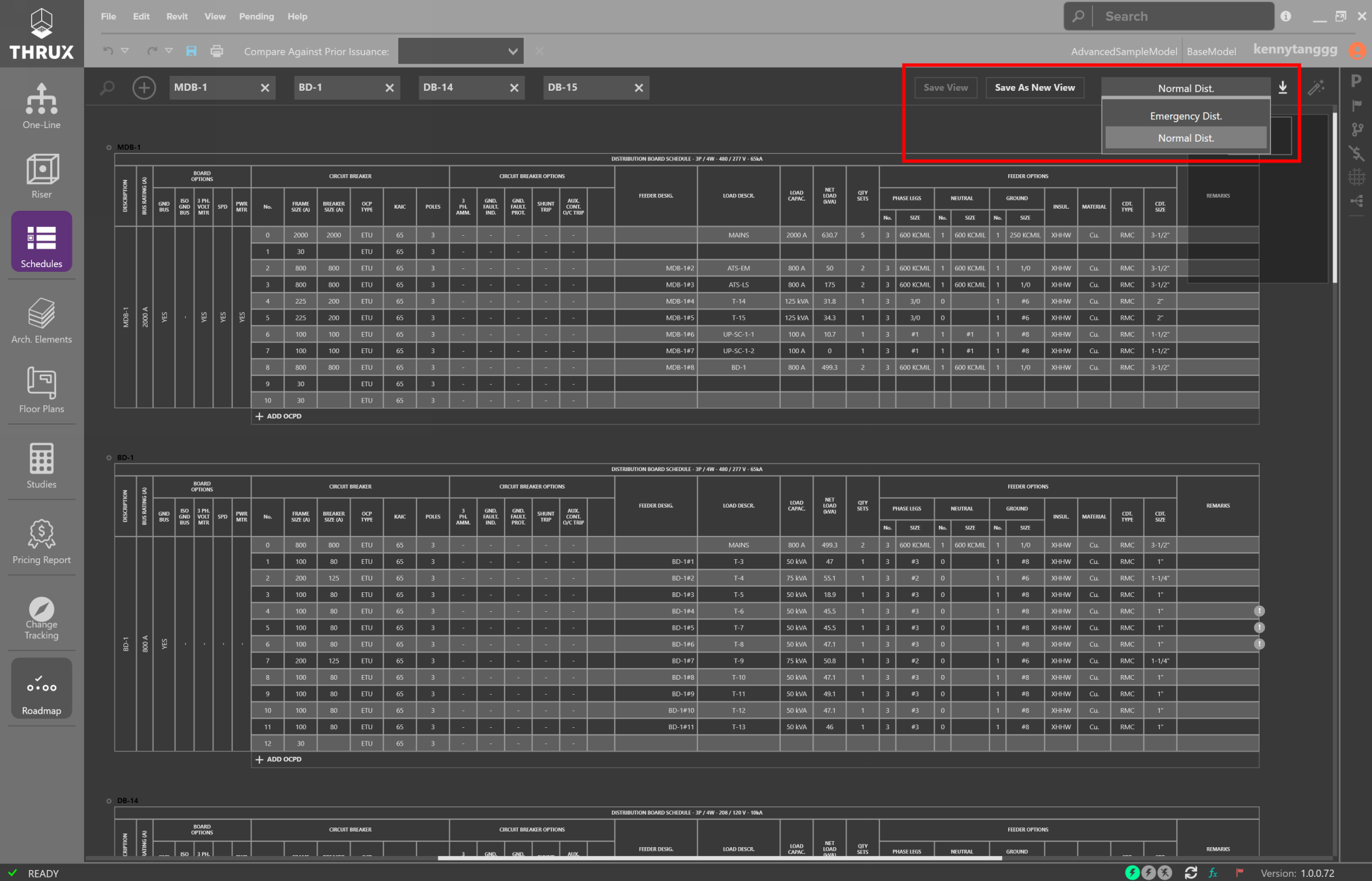
Saving Schedule Views allows groups of Schedules for later viewing
Exporting
Schedules are exportable to AutoCAD or Excel.
To export Schedules, click Export (down arrow) button in the top right of the Workspace.
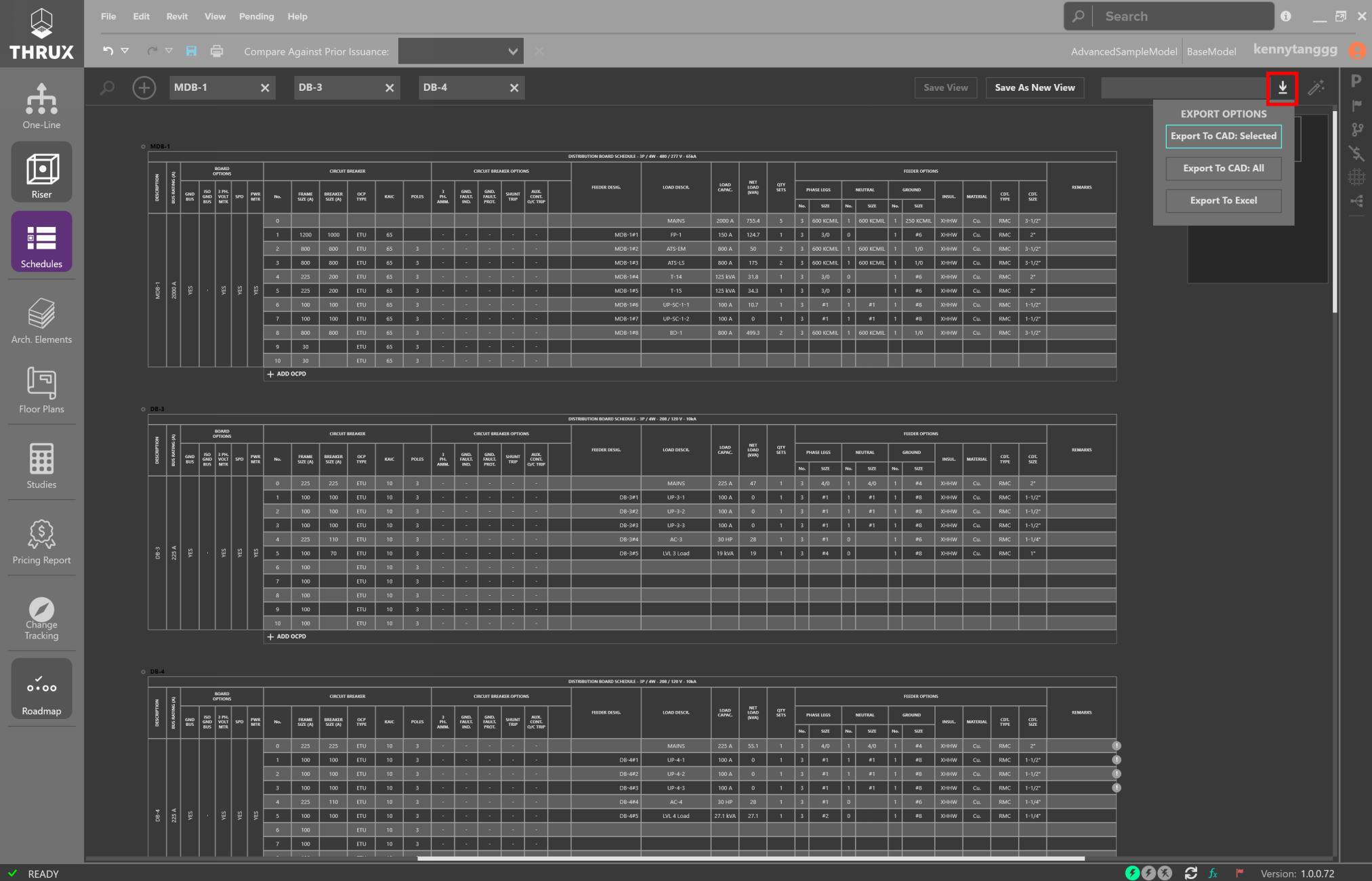
Exporting active Schedules
You have the option to export all of the active Schedules or all of the Schedules in the entire model.
Active Schedules are listed in the top.
Choose Export to AutoCAD: Selected
or
Export to AutoCAD: All.