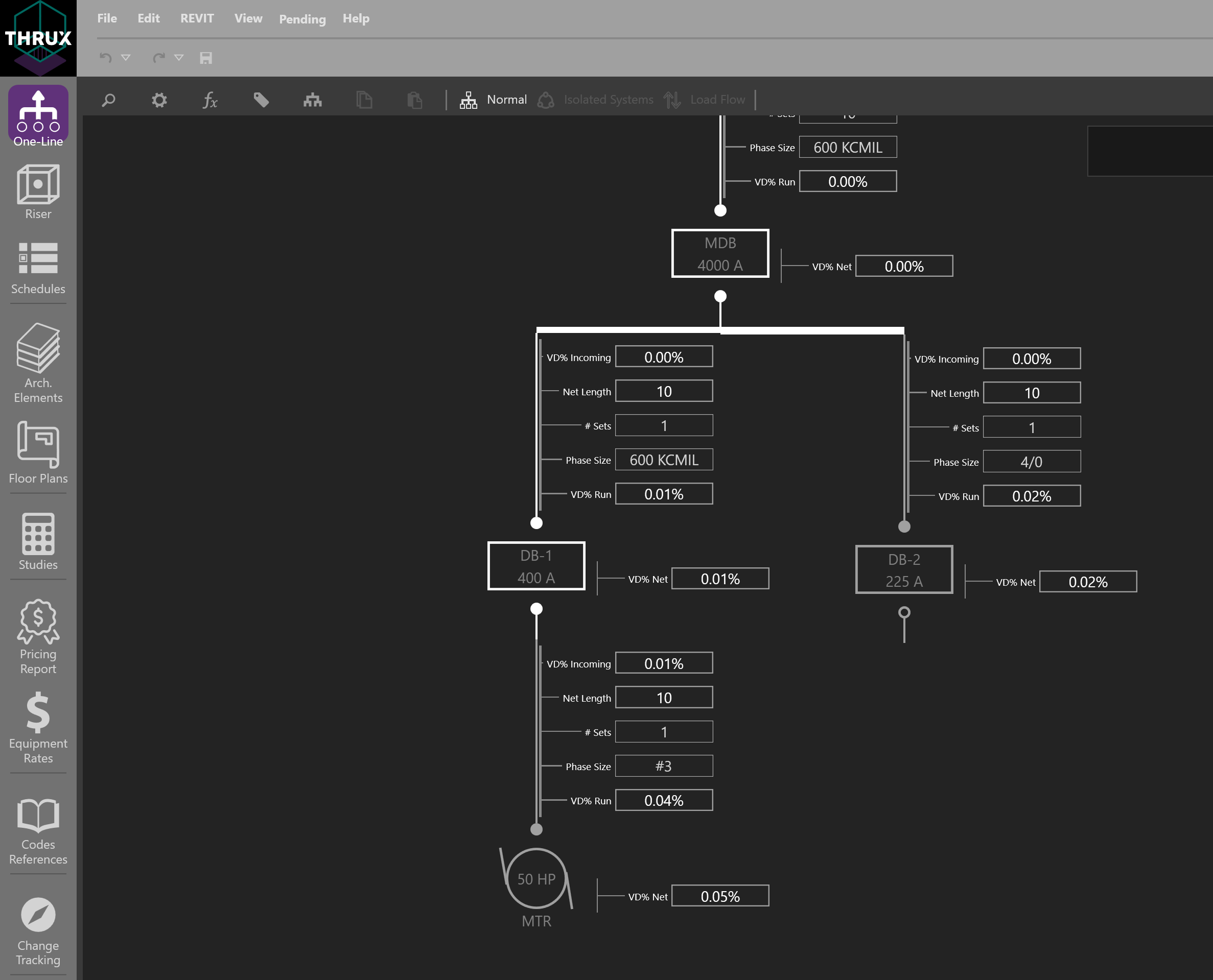
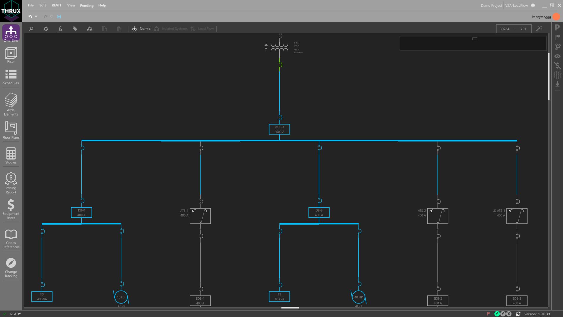
One-Line
The One-Line represents power flow of the distribution system shown from top to bottom, and generally consists of Sources, Distribution Equipment, and Loads. Types of sources include a Utility or a Generator.
Using the Workspace Toolbar on the left, click the One-Line icon to open the Workspace.
Hosted vs. Unhosted Systems
If a piece of Equipment is not fed from a source, then it is designated as Unhosted. During the stages of design, it is common to model hypothetical scenarios before all information is known. For example, as part of a larger project, an Architect may decide to create a space dedicated for a computer lab, but not yet decide on its exact location. While the location is not yet finalized, you can still model an Unhosted System with the intent of attaching the system to the main network in the future. Modeling Unhosted Systems allows flexibility when the source of a network is not yet known.
Add a Source
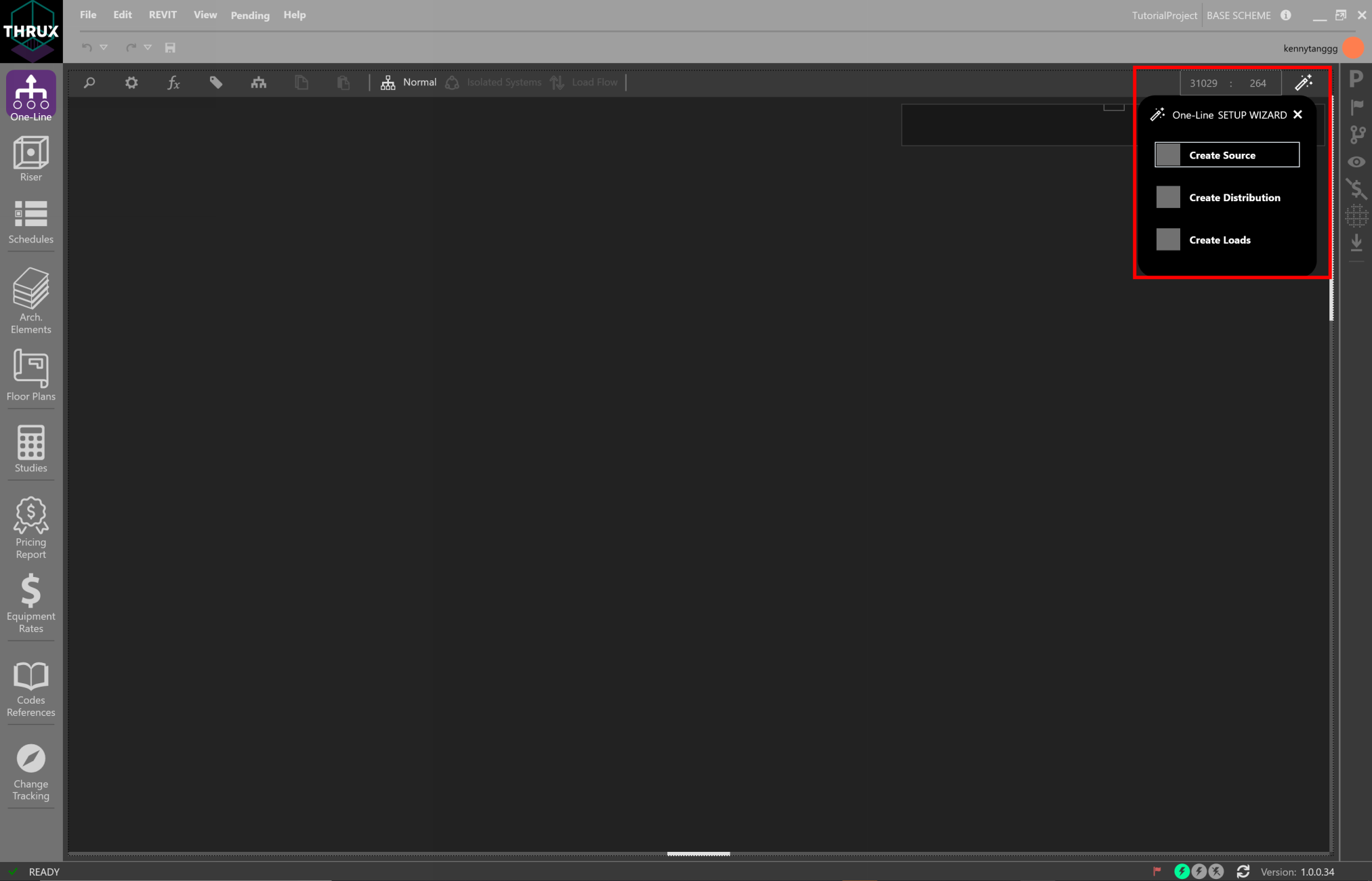
Use the Setup Wizard in the top right and select Create a Source.
Sources specify the level of short circuit current (SCC) that is potentially available in faulted systems. Short circuit current contributions could stem from the generator’s sub-transient reactance or the utility takeoff secondary terminals.
Using the Setup Wizard
Using the New Network wizard, create a Utility Equipment.
When using the New Network wizard, only the minimum pieces of information are required to create a piece of Equipment. This information will vary from Equipment to Equipment. For example, when creating a transformer the secondary voltage must be specified, but for a mechanical load only the size of the motor is required. More detailed properties can be specified and modified later.
Or right-click inside the Workspace, click Add Source, then click Utility Source.
Note that the ability to add Unhosted Equipment is available. Adding Unhosted Equipment can be used when the source of a network is unknown, or if you want to create segregated distribution networks and tie them together at a later time.
Short Circuit Current
Select the Utility source. Under the “Miscellaneous” property grouping, enter the value under Available SCC (kA).
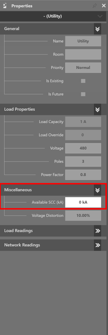
Entering Available SCC (kA)
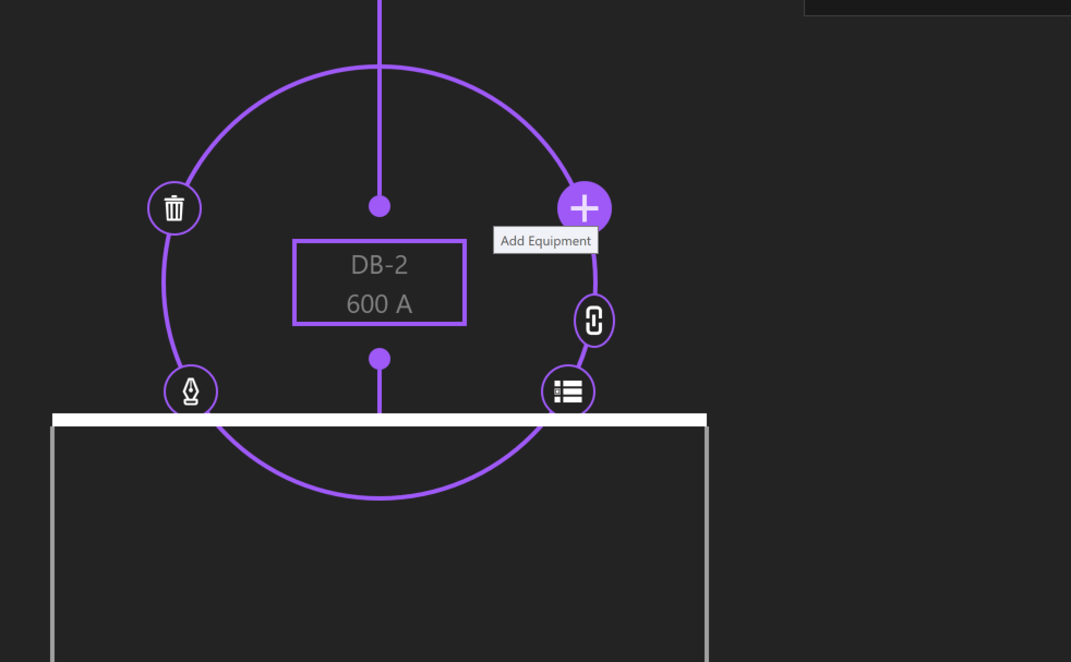
Add Equipment
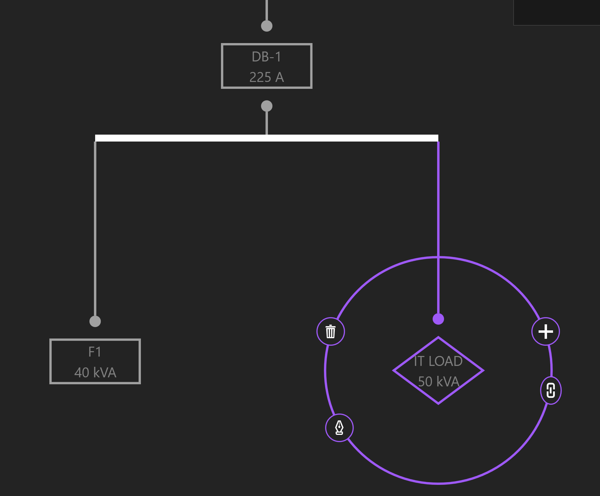
Click on the Utility and the Selection Dial will display a ring of options. Selected Equipment will be highlighted by a purple circle, with additional options to Add, Copy, Paste, Delete, and Navigate to other Workspaces. Click the + button to Add Equipment.
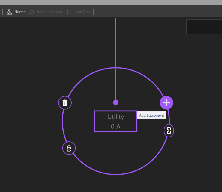
Selection Dial
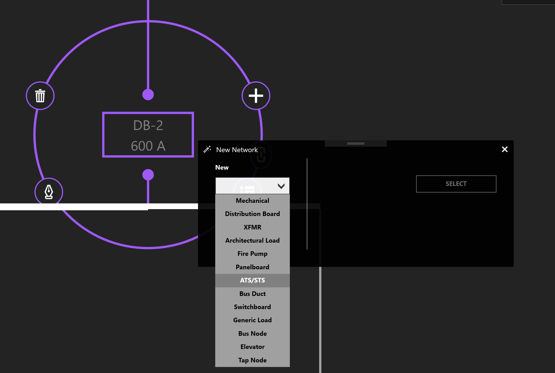
Select an Equipment type from the dropdown menu. Give the Equipment a name. In this case, specify a Load Capacity, and click Select.
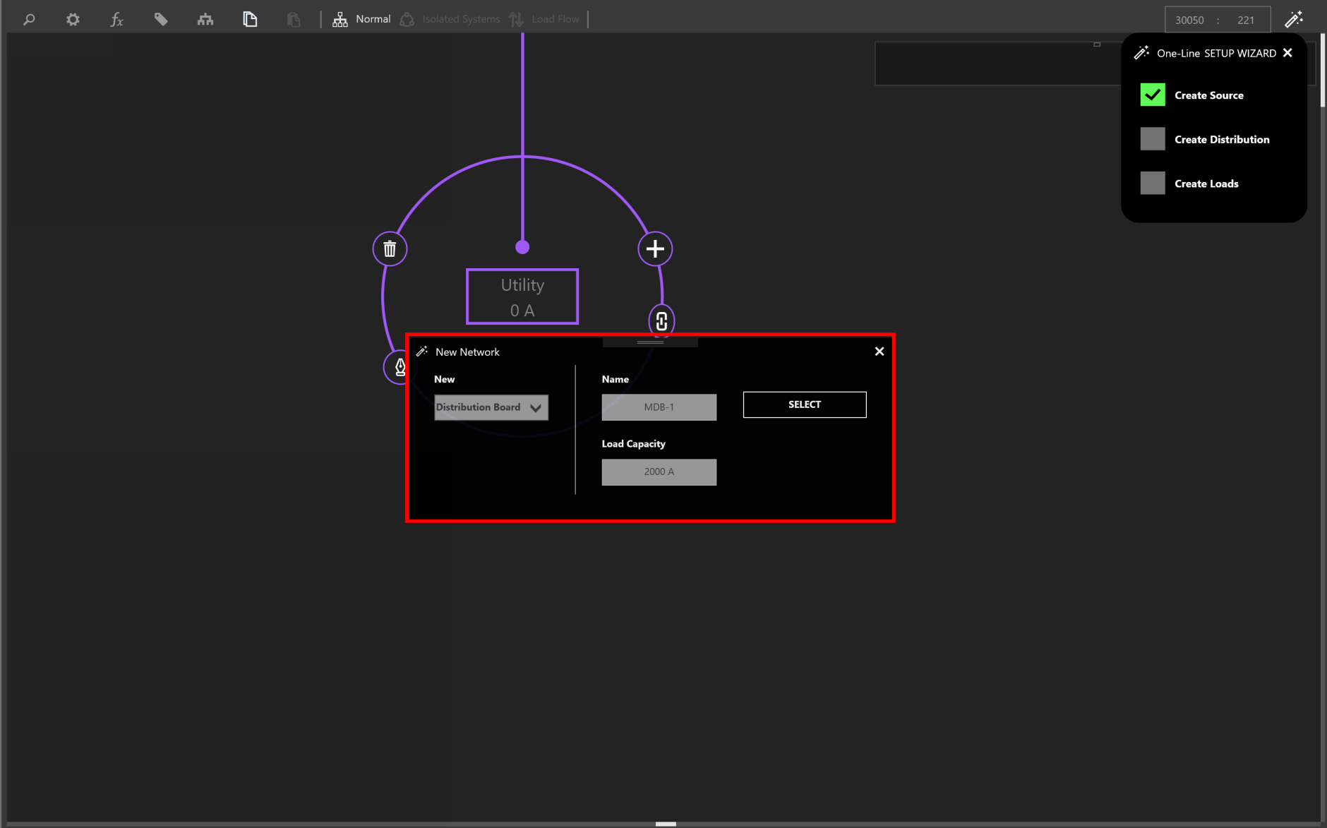
New Network Wizard
Copy/Paste Equipment
To copy Equipment, select the Equipment. Then, click Copy or use CTRL+C to copy. The selection will highlight pink and be added to the clipboard.
Then select the Equipment you want to create a pasted copy of, and click Paste or use CTRL+V.
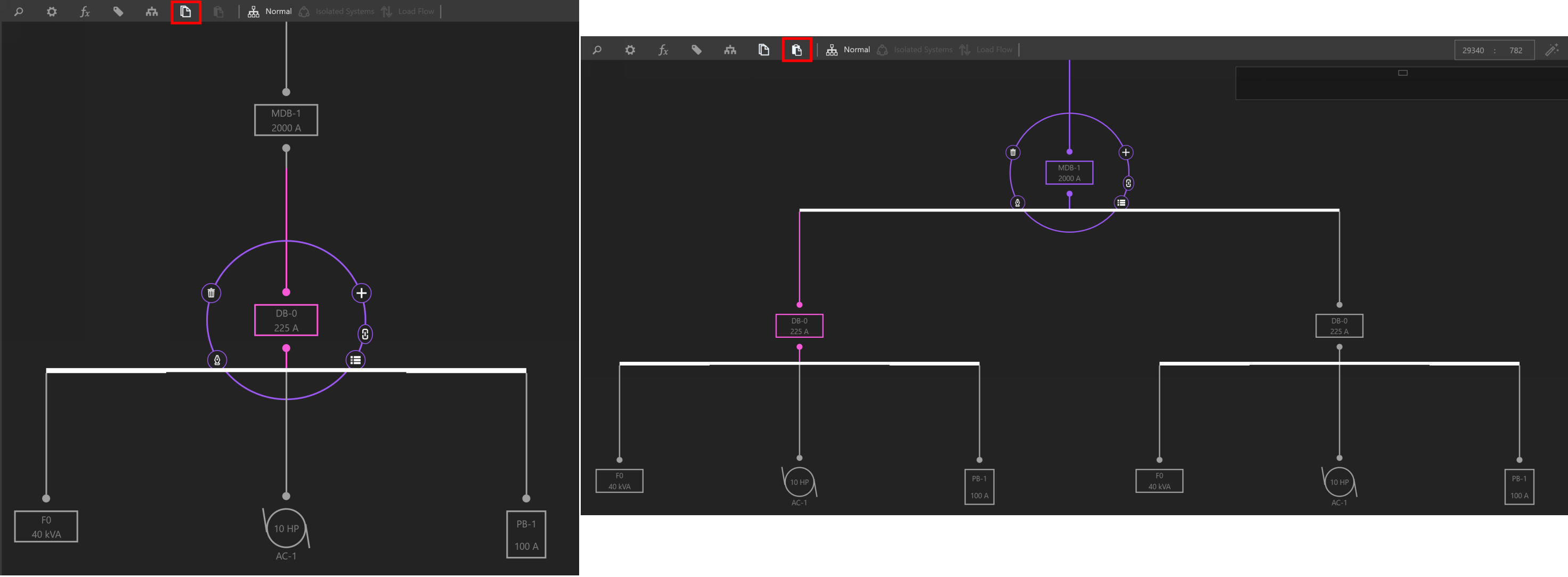
Copying an Equipment will copy its entire downstream network
Delete Equipment/Delete Network
To delete Equipment, select the Equipment. Then Click Delete (trash symbol) or use DEL to delete.
If the selected Equipment is feeding downstream Equipment, you have the option to either delete the selected Equipment or the entire network. Deleting Selected Equipment will only delete what is selected and any downstream equipment or children of the Selected Equipment will be disconnected and considered Unhosted.
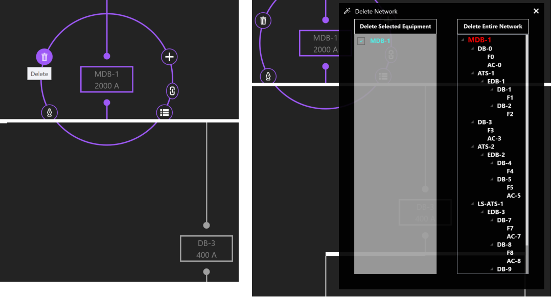
Deleting the selected Equipment or Entire Network
Dragging/Rehosting Equipment
To redirect an Equipment’s source, click and drag the Equipment from its current source to a different source.
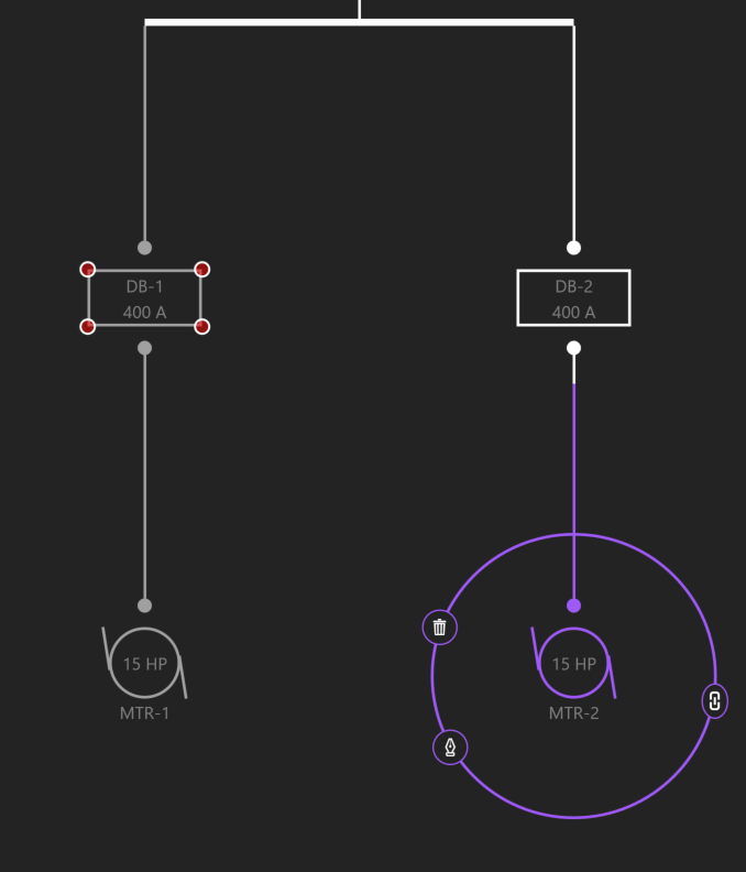
Rehosting MTR-2 to DB-1
Drop or release the Equipment on its new source.
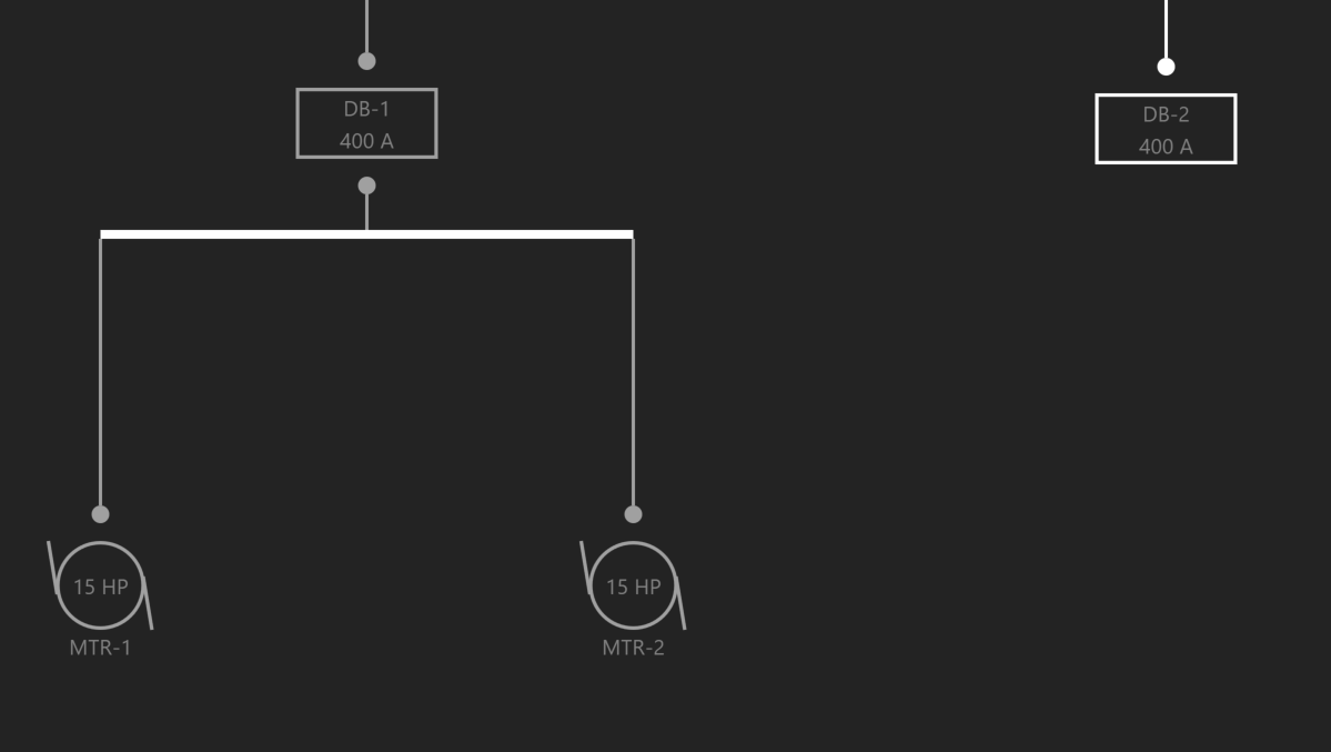
DB-1 now feeds MTR-1 and MTR-2
Navigate
Navigate grants the ability to jump between Workspaces based on the current selection.
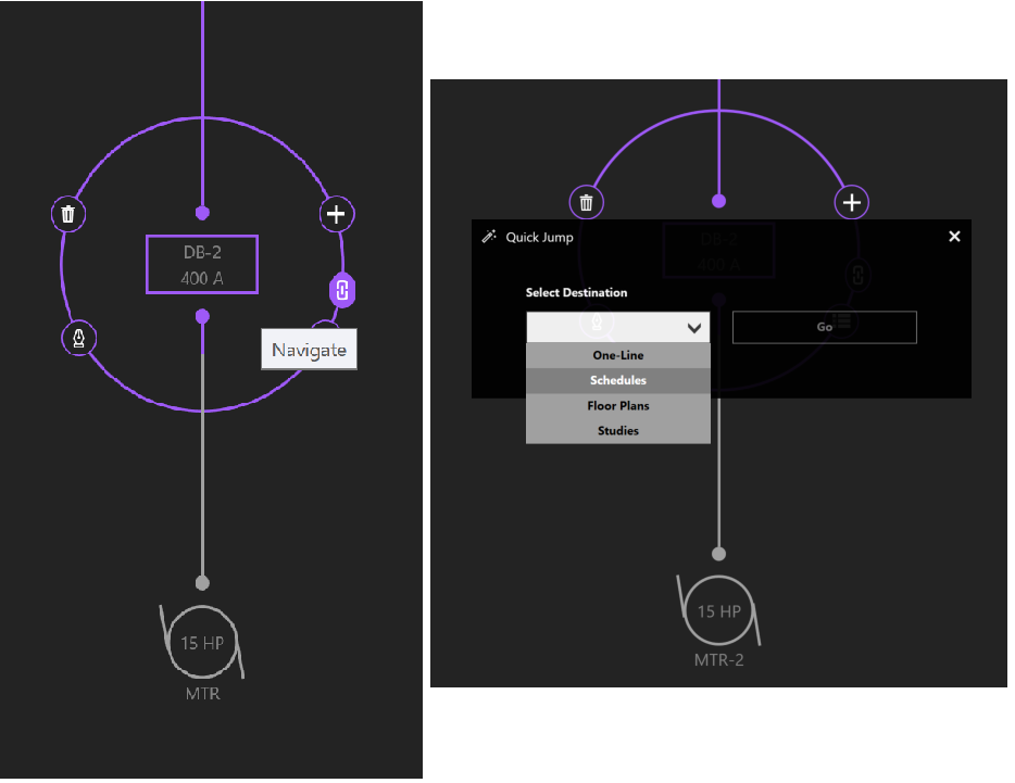
Using the Selection Dial to navigate to other Workspaces
Other examples of navigation include viewing an Equipment’s Schedule, location on the Riser, location on the Floor Plans, or the Studies Workspace.
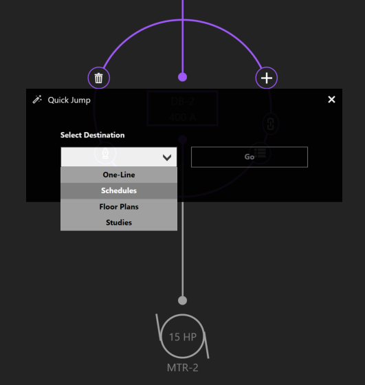
Navigating to the Schedules Workspace
Expanding/Collapsing Equipment
Sections of the distribution network can be expanded or collapsed on a group basis by using Expand All/Collapse All.
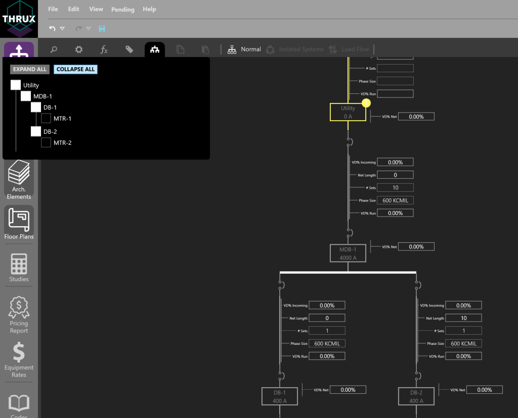
Using expand/collapse to visually maneuver the distribution network
Another way is by clicking on a distribution node, or double-clicking on the Equipment itself.
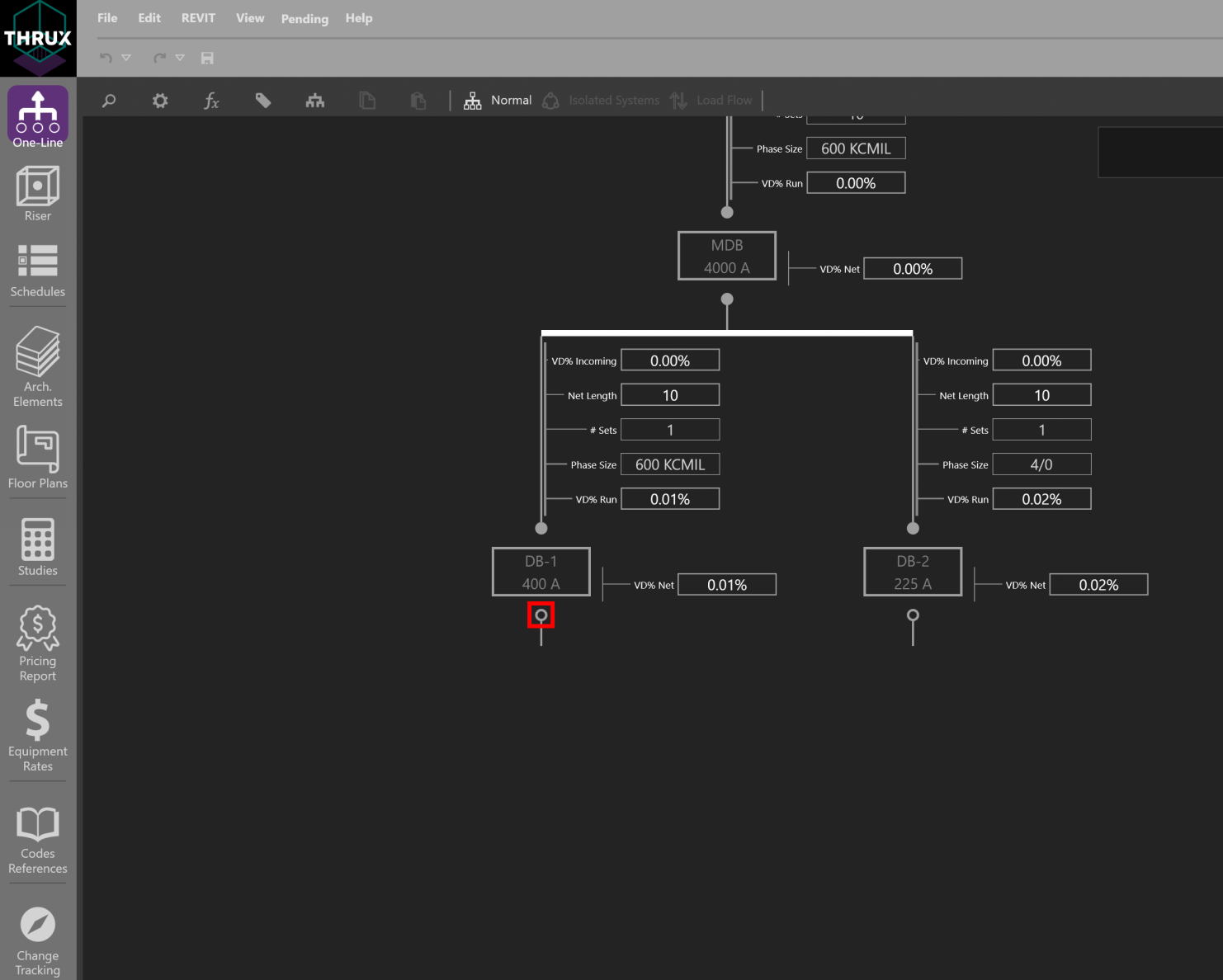
Clicking on a distribution node individually expands or collapses the network
A distribution node fills when it is fully expanded
Changing Multiple Equipment Properties
It is possible to change a property which is common across multiple elements.
First, drag a box to select multiple elements, or use CTRL+Click to select each element.
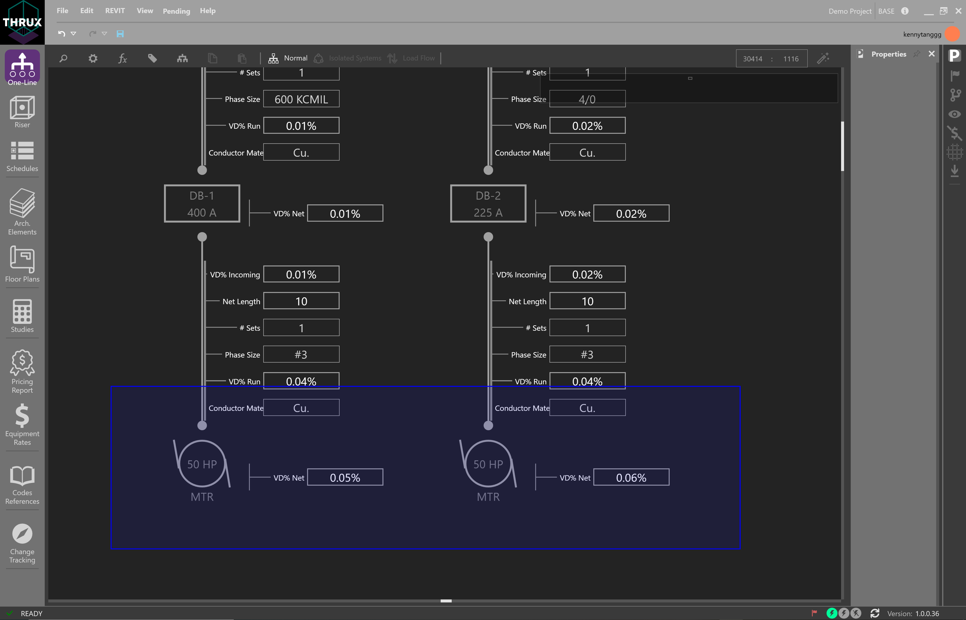
Selecting multiple motors by dragging and dropping a selection box
Then change a property such as Conductor Material from copper to aluminum.
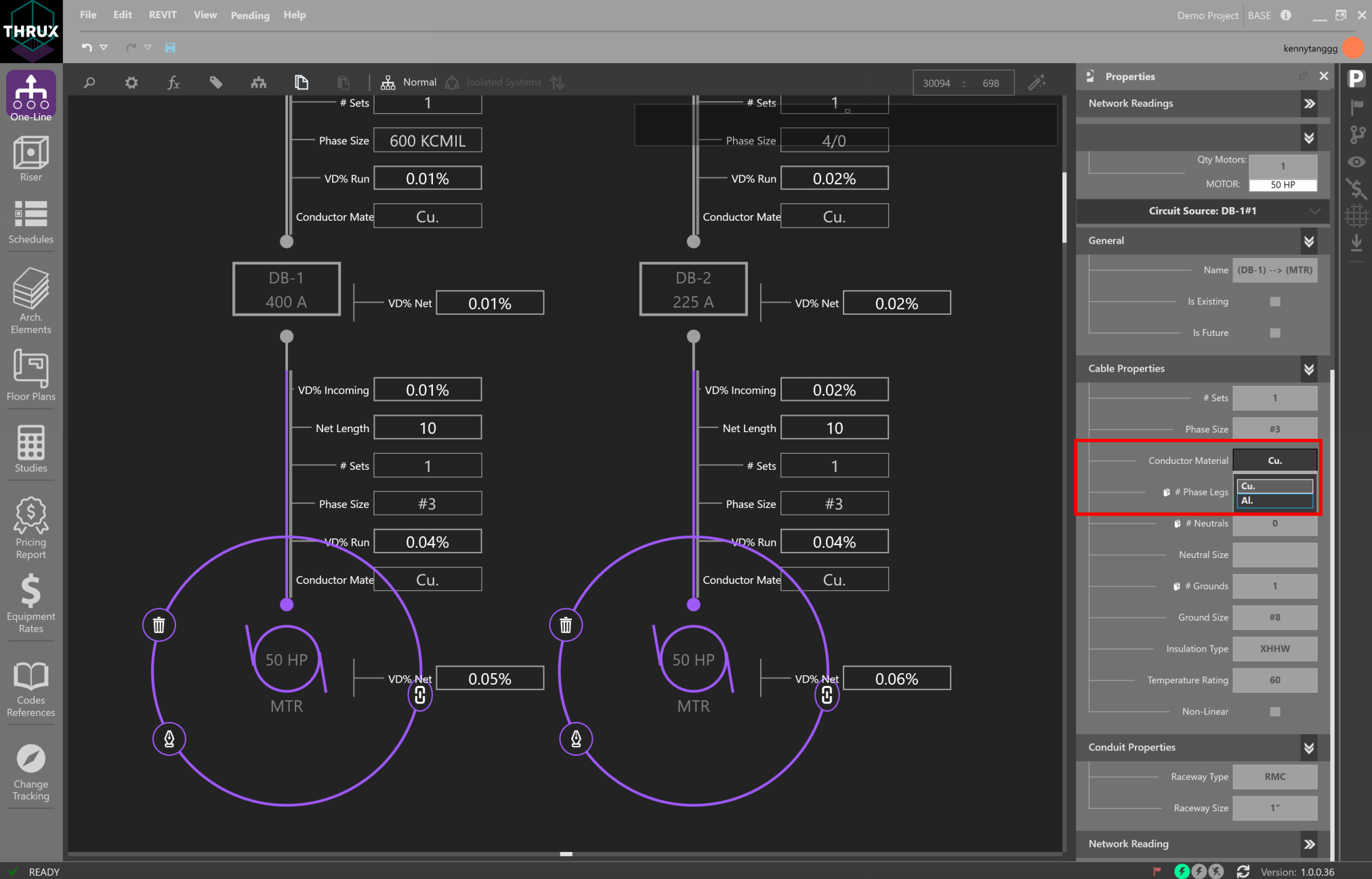
Using the Properties Explorer to change the Conductor Material
Note that since Design Assistance is on, the circuit’s code-minimum values are recalculated.
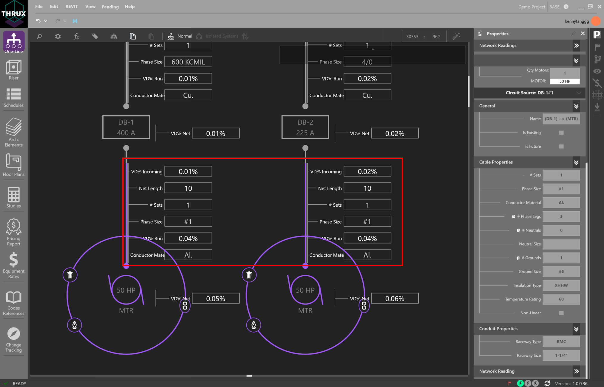
Viewing circuit properties as a result of changing the conductor material
Reset to Code Minimum
It is possible to manually modify circuit elements which cause a violation of safety codes and standards.
To recalculate or reset the values of a circuit to code-minimum values, right-click on an Equipment and use Reset to Code Minimum.
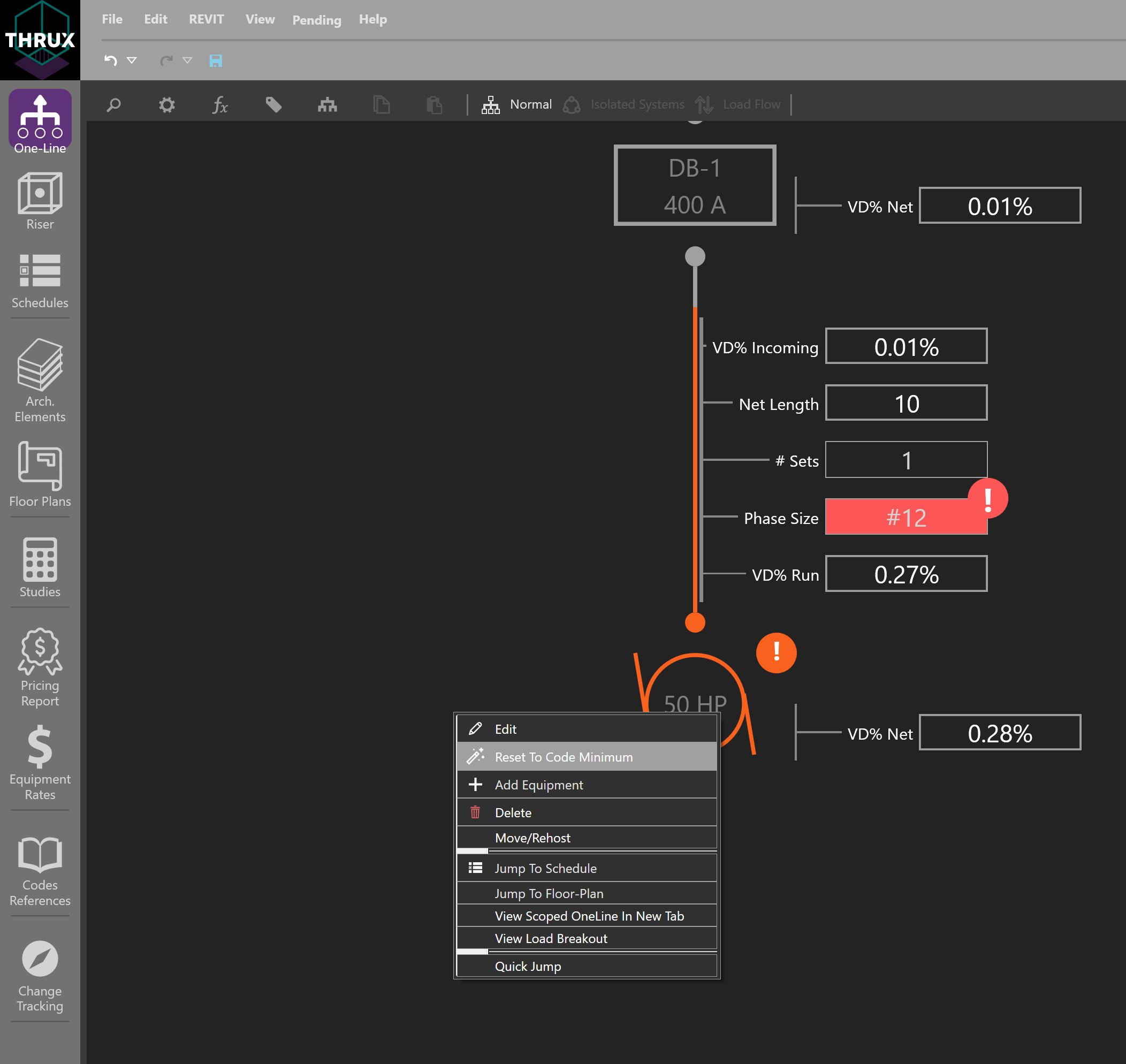
Using Reset to Code Minimum
Workspace Toolbox
Utility functions like searching, additional viewing properties, or calculation settings can be found on the Workspace Toolbox on the top toolbar.
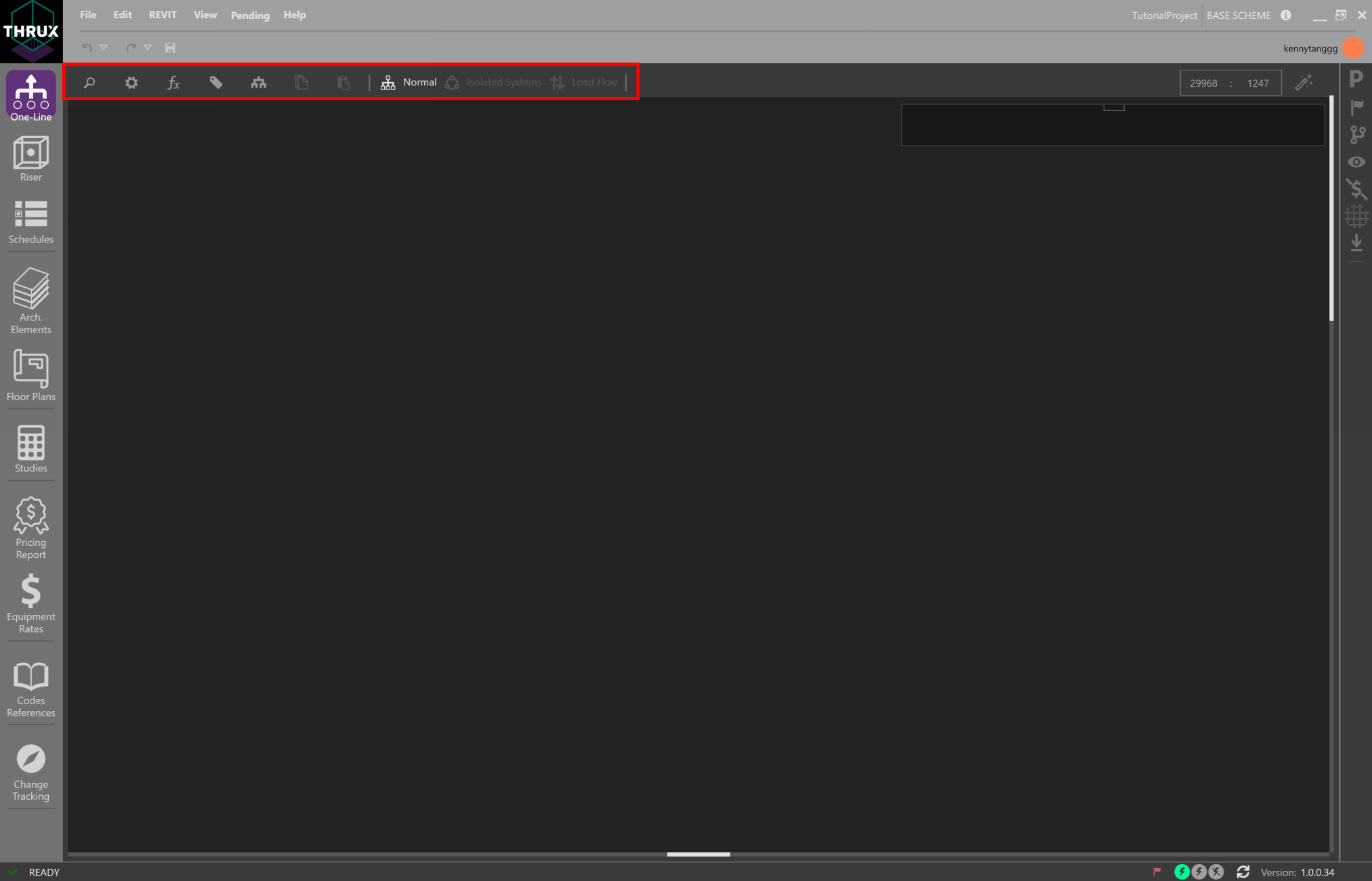
Workspace Toolbox
Searching
To search for Equipment, click the magnifying glass in the top left. Start to type the name of an Equipment. A dropdown will appear with any Equipment matching the specified name. Select the Equipment, and the Workspace will navigate to the associated Equipment.
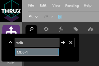
Searching for Equipment
Load Calculations
| Normal: | Calculations are based on the Net Load. |
|---|---|
| Board Capacity: | Calculations are based on 80% of the board’s Load Capacity. |
Property Tags/Quick Views
Property Tags can be applied to assist with design or network visualization. They provide flexibility with viewing specific properties of the model.
Click the tag symbol in the upper left of the Workspace Toolbox.
Quick Views are preset property groupings such as Voltage Drop, Loading, Load Diversification, and Circuit Routing.
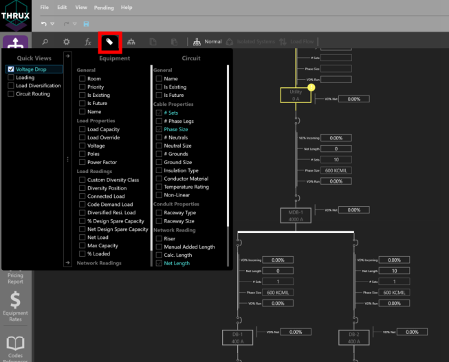
Property Tags
Assigning Room Locations
The distance between two pieces of Equipment are determined by their Room location via an orthogonal route. Open the Property Tags, and select Room.
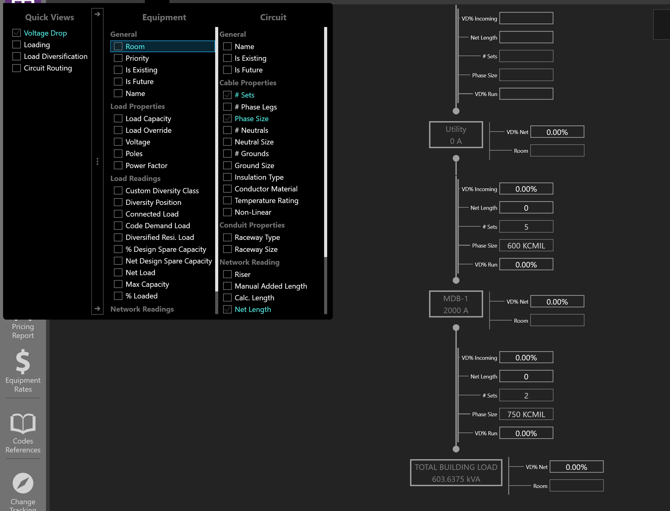
Using Property Tags to assign a Room
Assign a Room by clicking in the textbox. If no Rooms are available, create them using the Architectural Workspaces.
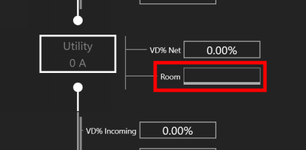
Using Property Tags to assign a Room
For the Distribution Board, MDB-1, note the Calc. Length before and after a Room location is assigned.
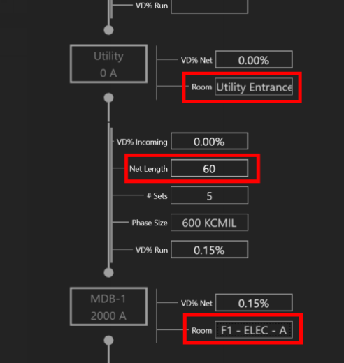
Using Property Tags to assign a Room
One-Line View Selectors
Different Views such as Isolated Systems and Load Flow can be applied to aid the designer.
By default, Normal is selected.
Load Flow
Load Flow is recommended when studying how a system is loaded.
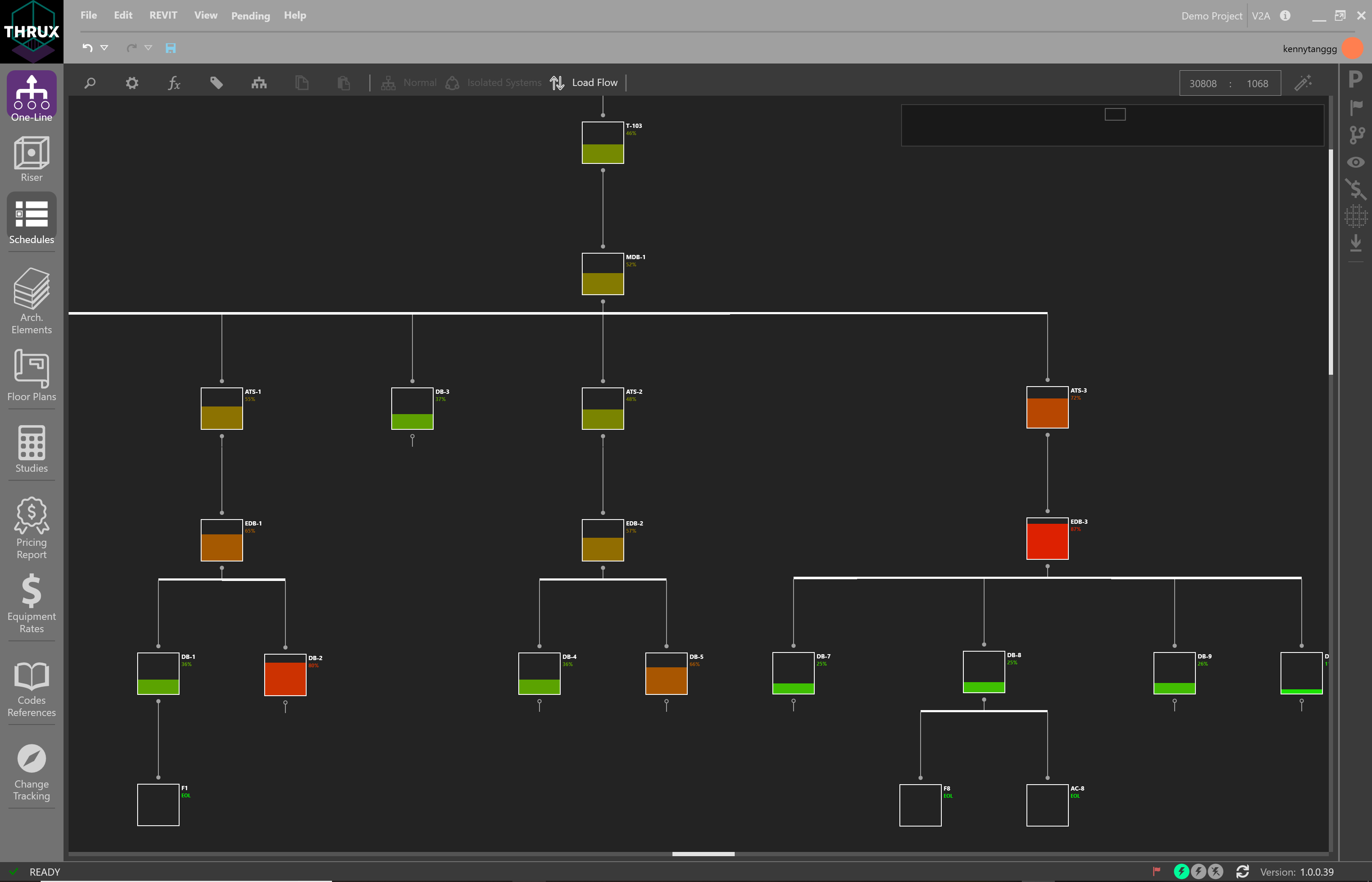
Using Load Flow view to diagnose loading concerns of the network.
Isolated Systems
Isolated Systems is recommended when viewing complex, redundantally distributed systems.
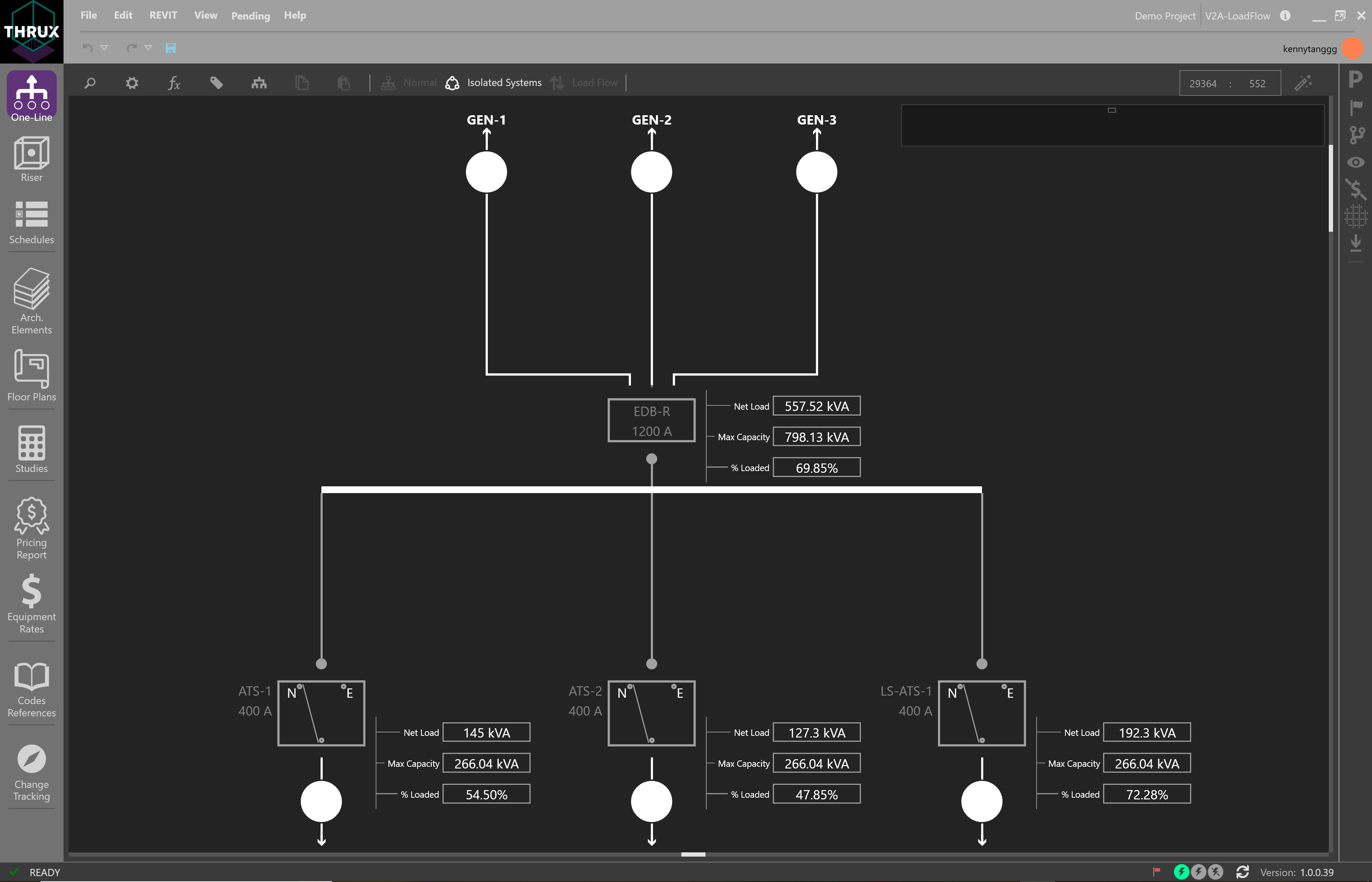
Using Isolated Systems to study loading as a result of different sources
Click on the arrow buttons to jump to the section of the distribution network.
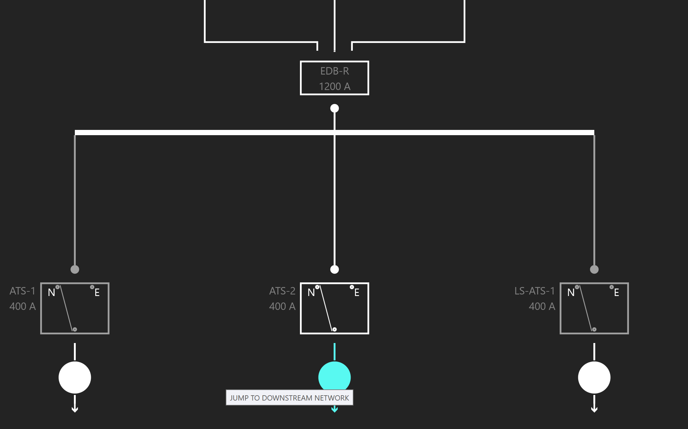
Navigating to a different section of the network
Creating a Transfer Switch
Transfer switches are connected to a primary and secondary source of power. To create a transfer switch, click Add Equipment and choose ATS/STS.
Using Selection Dial to Add Equipment
Creating a transfer switch
To connect the secondary source of power, choose another distribution Equipment. Then click Add Equipment and select an ATS/STS from the Existing dropdown menu.
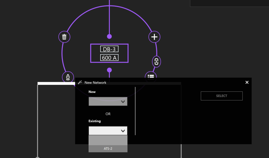
Connecting to an existing transfer switch
Settings
Toggle the visibility settings of OCPD’s by clicking on Show OCPD.
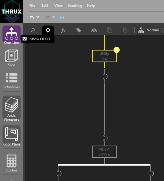
Showing OCPDs on the One-Line
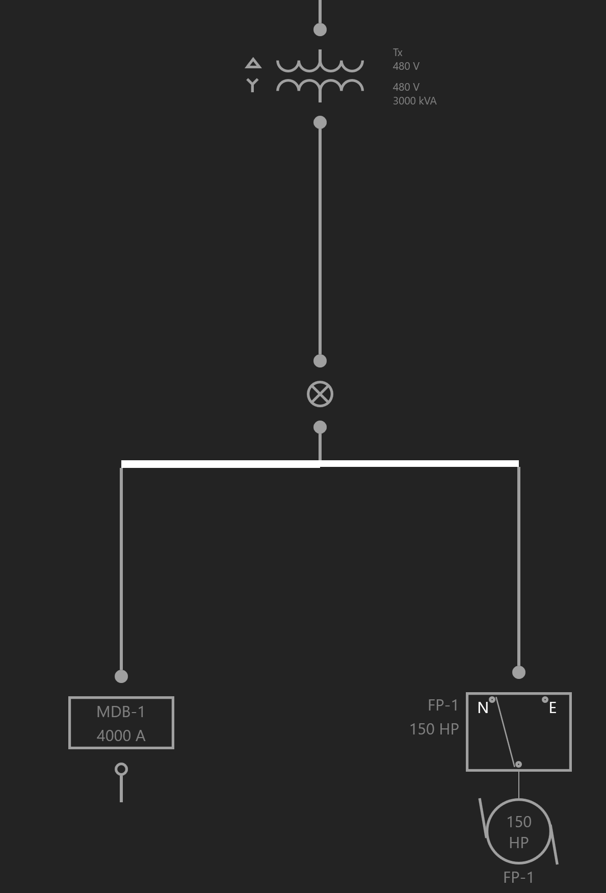
Open an OCPD by clicking on the OCPD.
An open breaker denotes an open circuit
Bus Duct
Select an Equipment. Then select Add Equipment to create a Bus Duct.
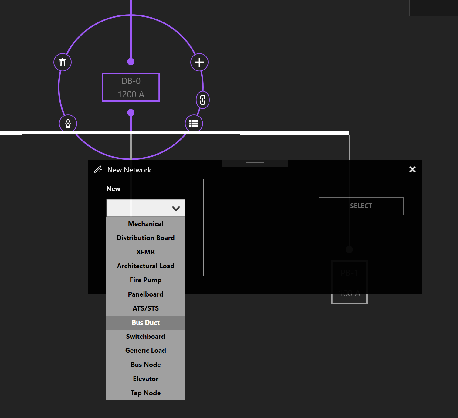
Using the New Network Wizard to create a Bus Duct
Visually, the representation of a Bus Duct is misleading and will be changed in an upcoming update. See here for a reference to how loading and voltage drop calculations apply to a Bus Duct.
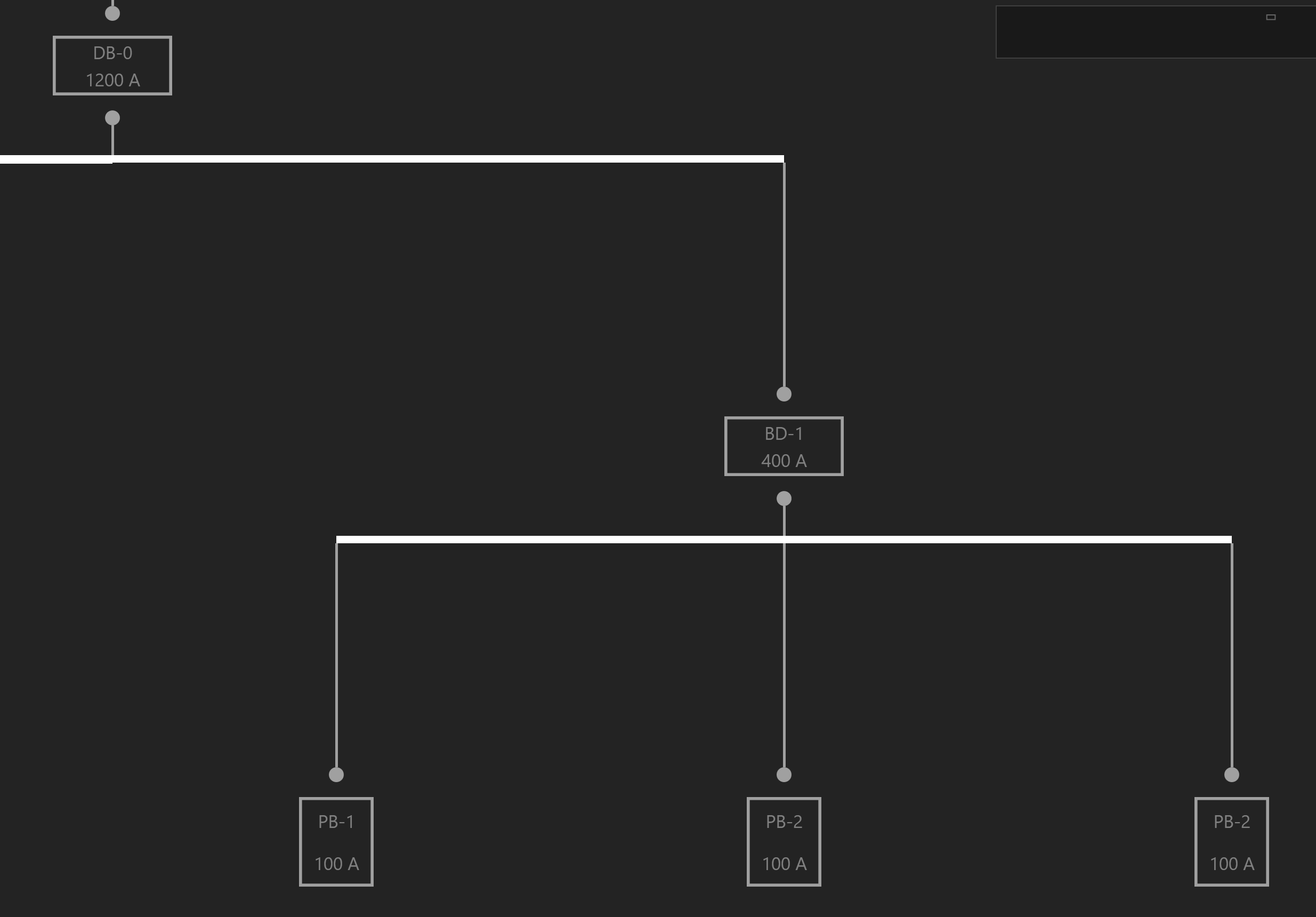
A Bus Duct with Panelboards as branch loads
Bus Node
To model a bus node, create a Bus Node in between the source and the load.
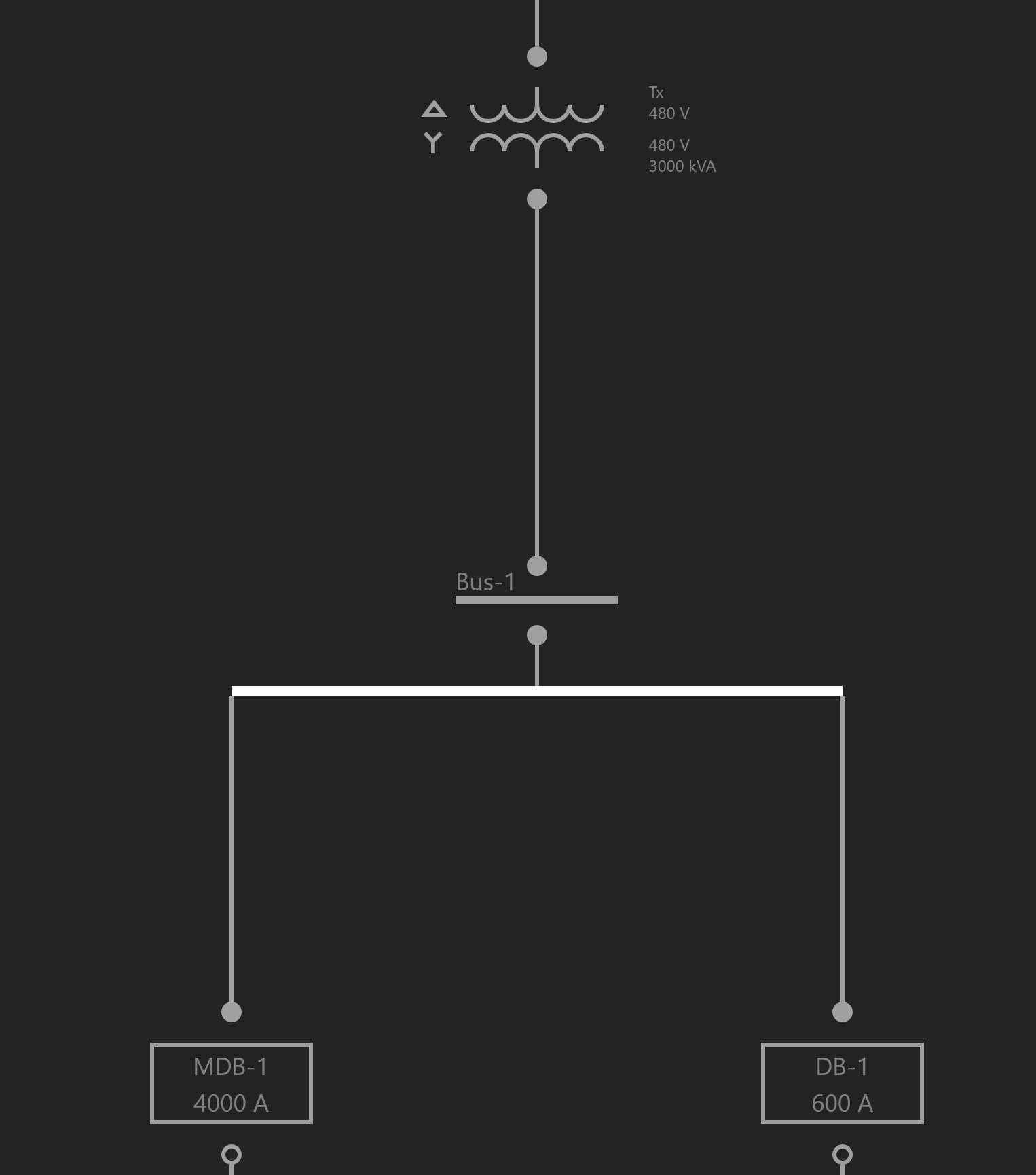
Creating a Bus Node in between an existing circuit
Elevator Loads
To model elevator loads, create an Elevator load. Loading diversities based on the NEC are dependent on the number of motors.
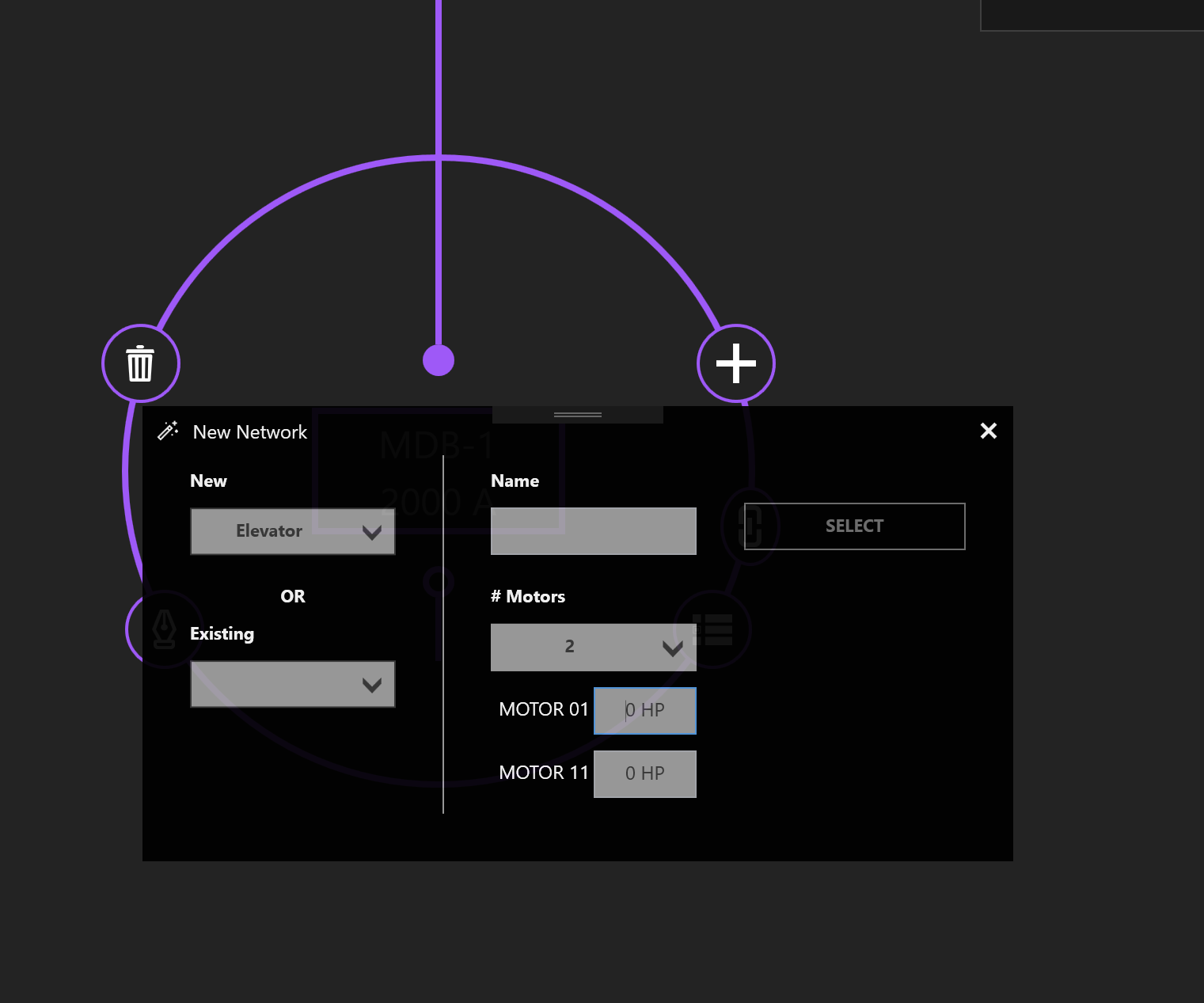
Creating an Elevator Load